Table of Contents Link to heading
- Hierarchical Network Design
- Scalable Network Design
- Reliable Network Design
- Network Device - Servers
- Server Placement
- Cisco Enterprise Architecture
Hierarchical Network Design Link to heading
Read more at 🔗
- Networks need to offer many different services to many different organisations, so the network design might have a wide range of variations.
- This might then lead to fairly complex and/or unique designs.
- Such complexity promises to make everyday maintenance and operation a demanding task. This is compounded when the network needs to expand.
- Fortunately, there are design guidelines that render the make-up of a network amenable to easy management and expansion.
- The following network design is arranged in layers that reflect their
functions:
- Access Layer: Offers users access to the network
- Distribution Layer: Distributes network traffic which caries the services of the network (e.g. connecting servers with users).
- Core Layer: If the services required by users are not found locally, users must exit the local network and travel to remote networks. Due to extensive travel, its characteristic is high-speed transmission of packets.
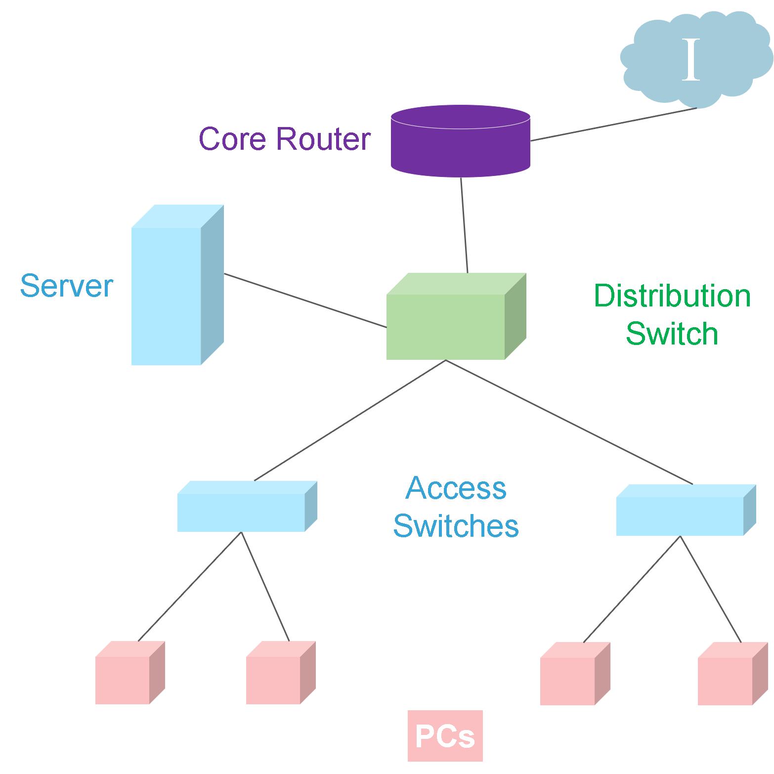
Scalable Network Design Link to heading
- When an expansion of the network is required, it helps if we consider the network as modular.
- Taking a look vertically, we can distinguish a typical structure of an Access Layer Switch connected to a Distribution Layer switch, which then connects to the various servers or router.
- This comprises the modular nature of the network, thus making it easily scalable.
- Any new module added to the current network is similar to the existing one, so staff are familiar with its construction, configuration, and performance.
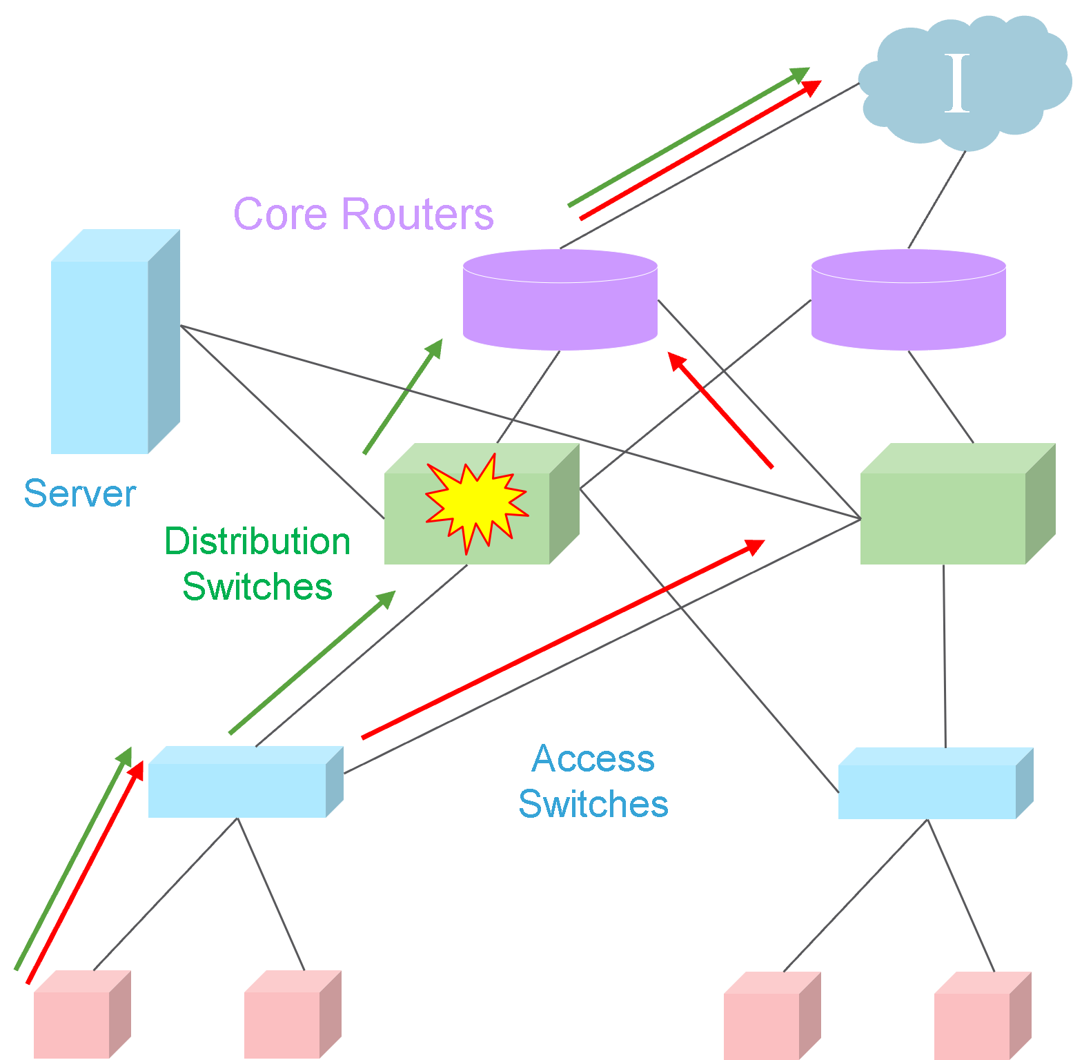
Reliable Network Design Link to heading
This modular design certainly solves the scalability issue, but it highlights another aspect.
The switches and router are single points of failure.
If the Distribution layer switch were to stop working, users would lose connectivity to the server and to the Internet.
The same can be said for the Core layer router and each Access layer switch.
By duplicating each device, we introduce the system of redundancy,
The devices are now not only doubled-up, but they are interconnected, thus offering users an alternate path out of the network or to the servers, if any of the Distribution or Core layer devices breaks down.
This arrangement of redundant devices, plus redundant links produces a fault-tolerant network which enables the system to continue operating properly while the network manager addresses the problem of the faulty device.
Network Device - Servers Link to heading
- We need to arrange for one more type of device into our network – a server.
- In fact, there are many services required – File servers, DHCP servers, Mail Servers, DNS, etc.
- Of course, we need redundancy to avoid a single point of failure.
- Therefore, we need to consider multiple servers and their proper placement within our network.
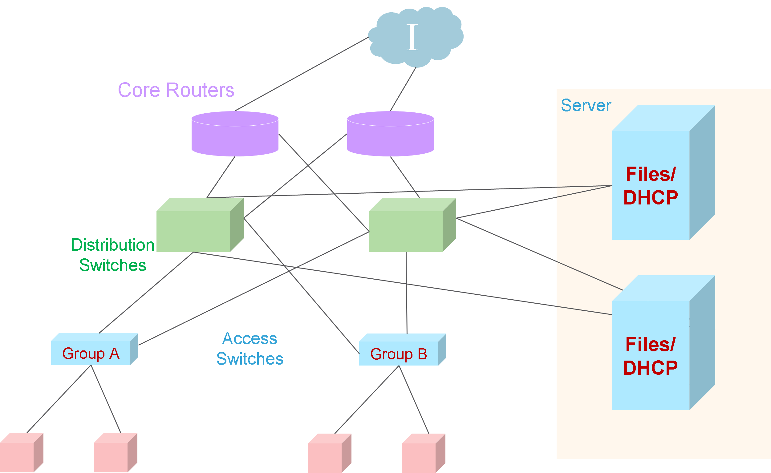
Server Placement Link to heading
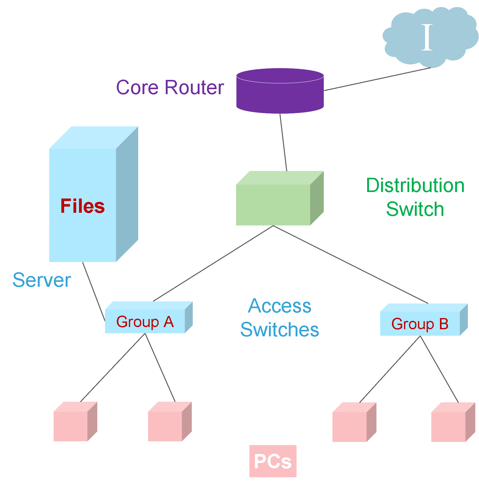
- If Group A users need a certain set of files and they are private, such a connection on the Group A Access switch as shown, is totally adequate.
- However, if Group B also needs access to these files, the path to the server is rather tortuous.
- If the server were a DHCP server, Group B users would certainly need to wait longer to log in than Group A users.
- So a possible solution would be moving the server to a Distribution Layer switch.
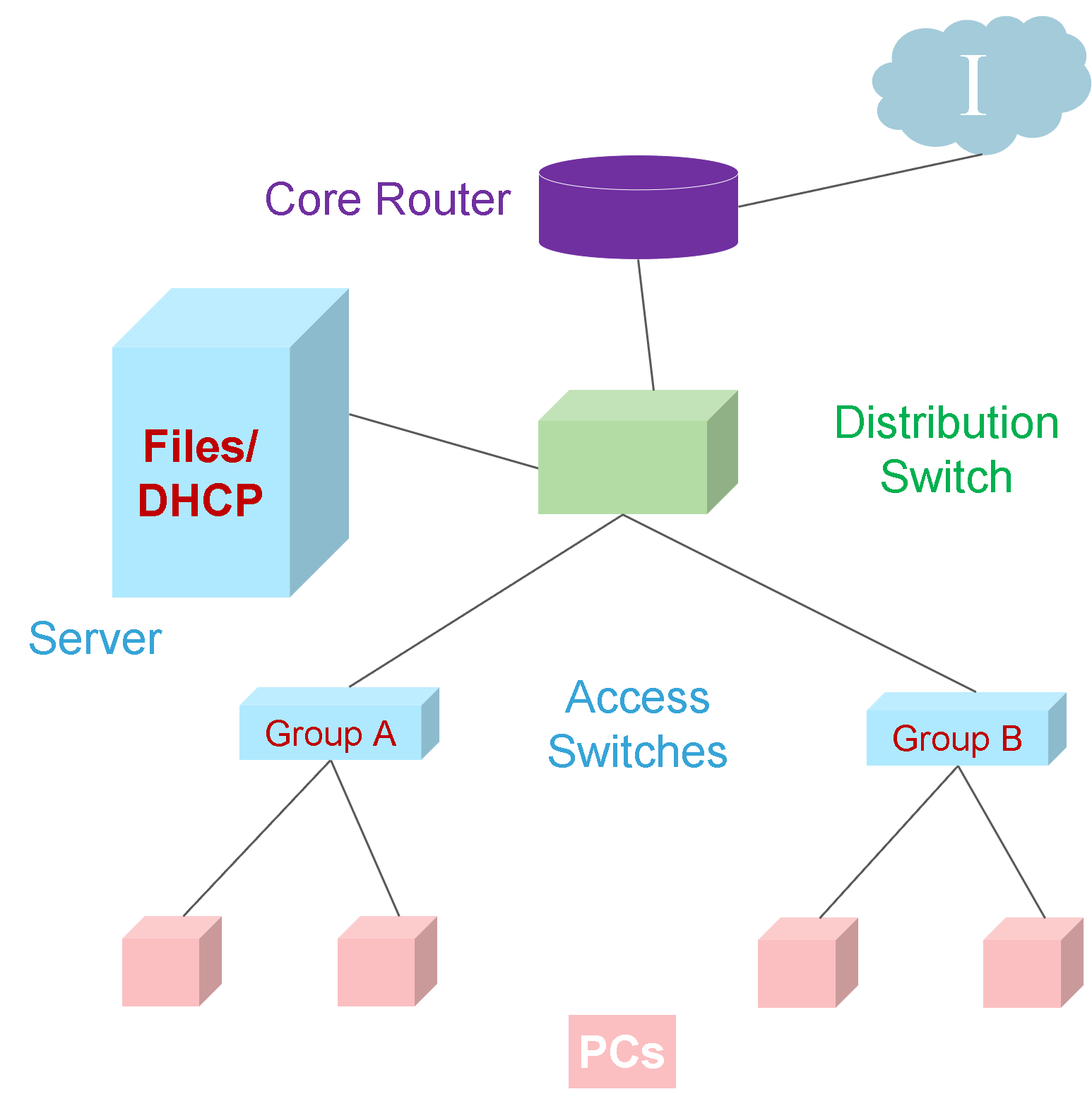
- However, this is an unreliable design due to a single point a failure.
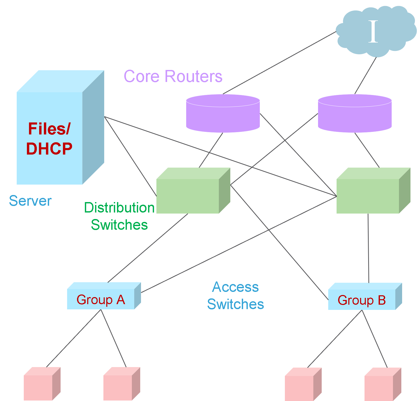
- Hence a redundant link to redundant distribution layer switch.
- To enforce redundancy further for increased reliability, a redundant server can be added.
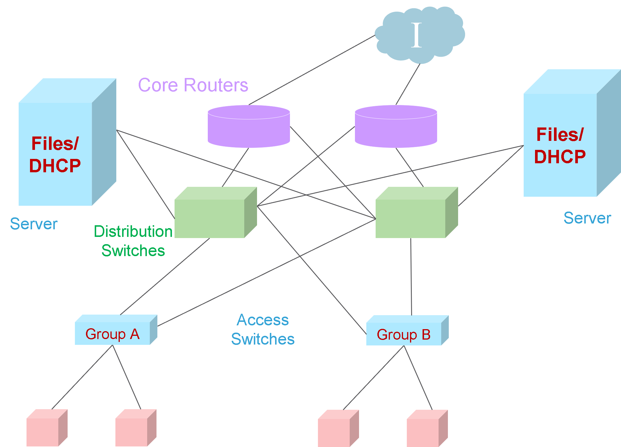
- Instead of separating the servers, combine them into a Server Farm.
- To develop the Server Farm concept, investigate the Data Centre design.
- A Data Centre is a globally coordinated network of devices designed to accelerate the delivery of information over the Internet infrastructure.
Cisco Enterprise Architecture Link to heading
divides the network into functional components while still maintaining the Core, Distribution, and Access layers.
As the figure below shows, the primary Cisco Enterprise Architecture modules include
- Enterprise Campus
- Enterprise Edge
- Service Provider Edge
- Remote
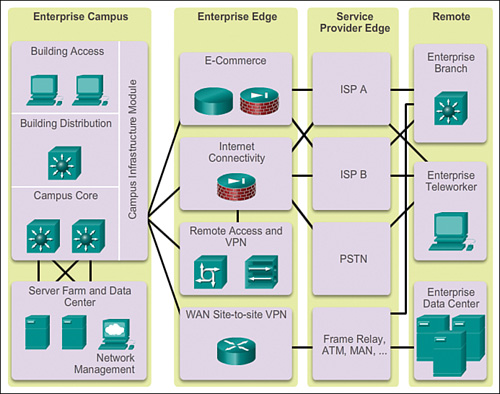
Enterprise Camppus Link to heading
consists of the entire campus infrastructure, to include the Access, Distribution, and Core layers.
The Access layer module contains Layer 2 or Layer 3 switches to provide the required port density. Implementation of VLANs and trunk links to the building Distribution layer occurs here. Redundancy to the building Distribution switches is important. The Distribution layer module aggregates building Access using Layer 3 devices. Routing, Access control, and QoS are performed at this Distribution layer module. The Core layer module provides high-speed interconnectivity between the Distribution layer modules, Data Centre, Server Farms, and the Enterprise Edge. Redundancy, fast convergence, and fault tolerance are the focus of the design in this module.
In addition to these modules, the Enterprise Campus can include other submodules:
- Server Farm and Data Centre Module: This area provides high-speed connectivity and protection for servers. It is critical to provide security, redundancy, and fault tolerance. The network management systems monitor performance by monitoring device and network availability.
- Services Module: This area provides Access to all services, such as IP Telephony services, wireless controller services, and unified services.
Enterprise Edge Link to heading
consists of the Internet, VPN, and WAN modules connecting the enterprise with the service provider’s network.
This module extends the enterprise services to remote sites and enables the enterprise to use Internet and partner resources. It provides QoS, policy reinforcement, service levels, and security. Service Provider Edge
Service Provider Edge Link to heading
provides Internet, Public Switched Telephone Network (PSTN), and WAN services.
All data that enters or exits the Enterprise Composite Network Model (ECNM) passes through an edge device. This is the point where all packets can be examined and a decision made whether the packet should be allowed on the enterprise network. Intrusion detection systems (IDS) and intrusion prevention systems (IPS) can also be configured at the enterprise edge to protect against malicious activity.
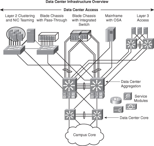
Data Centre Infrastructure Link to heading
There are three layers of the data centre design:
- Core layer: Provides a high-speed packet switching backplane for all flows going in and out of the data centre.
- Distribution layer: Provides important functions, such as L2 domain definitions, spanning tree processing, default gateway redundancy, and service module integration (e.g., security, load balancing, content switching, firewall, SSL offload, intrusion detection, and network analysis).
- Access layer: Connects servers physically to the network.
Multitier HTTP-based applications supporting web, application, and database tiers of servers dominate the multitier data centre model. The access layer network infrastructure can support both L2 and L3 topologies, and L2 adjacency requirements fulfilling the various server broadcast domain or administrative requirements. L2 in the access layer is more prevalent in the data centre because some applications support low-latency via L2 domains. Most servers in the data centre consist of single and dual attached one rack unit (RU) servers, blade servers with integrated switches, blade servers with pass-through cabling, clustered servers, and mainframes with a mix of oversubscription requirements