Table of Contents Link to heading
- Key Design Principles
- Scalability
- Redundancy
- Fault Tolerance
- Security
- Reducing Failure Domain Size
- Link Aggregation
- Expanding the Access Layer
- Expanding the Distribution Layer
- Expanding the Core Layer
- Fine-tuning Routing Protocols
- Campus Network
- Enterprise Network
- Dedicated Network Areas
Key Design Principles Link to heading
Follow these key design principles to serve as the basis for developing network designs.
| Design Principle | Description |
|---|---|
| Hierarchy | Designing a scalable network using a layered, modular model |
| Redundancy | Duplicating devices, services, or connections so that, if a failure occurs, the redundant devices, services, or connections can perform the work of those that failed |
| Modularity | Separating different devices, services, and technologies (e.g., enterprise campus, services block, data centre, Internet edge) into modules |
| Security | Integrating security throughout to protect business data |
| Performance | Providing enough capacity and bandwidth for applications |
| Cost | Balancing the amount of security and technologies with the budget |
| Availability | The amount of time a network is available to users, often expressed as a percent uptime, or as a mean time between failure (MTBF) and mean time to repair (MTTR) |
| Adaptability | The ease with which a network design and implementation can adapt to network faults, changing traffic patterns, additional business or technical requirements, and other changes |
| Scalability/Flexibility | How easily the network can modify one segment, add new services, or accommodate more users and data transmission requirements without going through a major forklift upgrade (i.e. replacing major hardware devices) |
| Manageability | Ease of managing and maintaining the infrastructure |
| Reliability | The extent to which a network or computer system provides dependable, error-free service |
| Standards and Regulations | Compliance with applicable laws, regulations, and standards |
- High availability is often what most businesses and organisations strive for in sound network designs, given that it leads to reliability and resiliency,.
- The key components of application availability are response time and
throughput.
- Reponse time is the amount of time between a request for some network service and a response to the request.
- Real-time applications, such as voice and video, are not very tolerant to jitter and delay.
- Reliability is often measured as a probability of failure or as the mean time between failures (MTBF).
Scalability Link to heading
Network designers must develop strategies to enable the network to be available and to scale effectively and easily. This is accomplished using:
- Redundancy
- Multiple Links
- Wireless Connectivity
- Scalable Routing protocol
One way to scale up is to connect various locations by using common security measures - The Cisco Borderless Network is a next-generation architecture that can connect anyone, anywhere, anytime, on any device securely, reliably, and seamlessly.
- It provides the framework to unify wired and wireless access, built on a hierarchical infrastructure of hardware that is modular, scalable and resilient.
- Access is via User authentication.
Redundancy Link to heading
Redundancy can be done by minimising the possibility of a single point of failure, which means:
- Installing duplicate equipment
- Installing duplicate links to network devices
- Providing failover services for critical devices
There are four models of redundant network.
Workstation-to-Router Redundancy Link to heading
- Address Resolution Protocol (ARP)
- Explicit configuration
- Router Discovery Protocol (RDP)
- Routing Information Protocol (RIP)
- Internetwork Packet Exchange (IPX)
- AppleTalk
- Hot Standby Router Protocol (HSRP)
Server Redundancy Link to heading
For example, in a brokerage firm where traders must access data in order to buy and sell stocks, the data can be replicated on two or more redundant servers. Each server should be on its own network and power supply.
If complete server redundancy is not feasible due to cost considerations, mirroring or duplexing of the file server hard drives is a good idea.
- Mirroring means synchronising two disks.
- Duplexing is the same as mirroring with the additional feature that the two mirrored hard drives are controlled by different disk controllers.
Route Redundancy Link to heading
- To support load balancing, keep the bandwidth consistent within a layer of the hierarchical model so that all paths have the same cost (Cisco’s IGRP and EIGRP are exceptions).
- A hop-based routing protocol does load balancing over unequal bandwidth paths as long as the hop count is equal.
- Another reason to keep bandwidth consistent within a layer of a hierarchy is that routing protocols converge much faster if multiple equal-cost paths to a destination network exist.
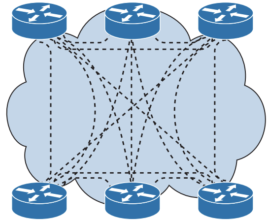
A network can be designed as a full mesh or a partial mesh.
- In a full mesh architecture, each router has a link to every other router, as shown in the topology below.
- A full mesh network provides complete redundancy and also provides good
performance because there is just a single-hop delay between any two sites.
- There is no logical loop as L3 has the time-to-live (TTL) value, hence no need for spanning tree protocol.
- The number of links in a full mesh is
n*(n–1)/2, where n is the number of routers.- Dividing the result by 2 avoids counting Router X to Router Y and Router Y to Router X as two different links.
- In the following topology, the number of links = 6*5)/2=15 circuits.
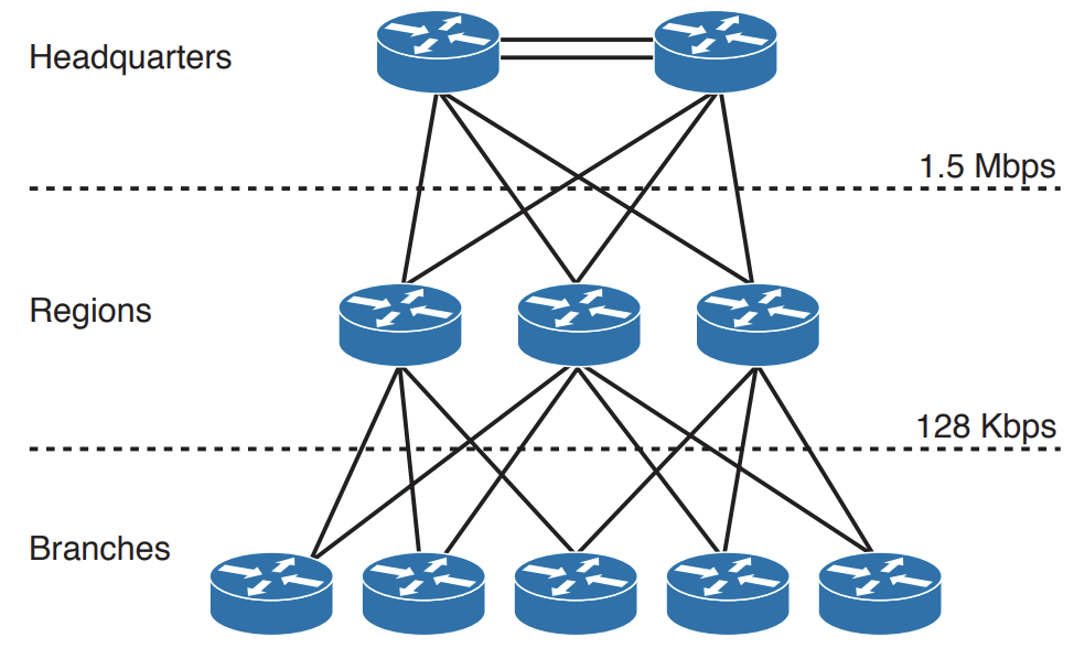
- For LAN designs, it may not be necessary and even is even expensive to implement a full mesh network due to the required number of links.
- In this case, a partial mesh architecture is more appropriate.
- As in the topology below, links between the Access and Distribution layer can be Fast Ethernet, while links to the core are at Gigabit Ethernet speeds.
Link Media Redundancy Link to heading
In switched networks, switches can have redundant links to each other. This redundancy is good because it minimises downtime and supports high availability, but it may result in logical L2 loops, hence the usage of Spanning Tree Protocol (STP).
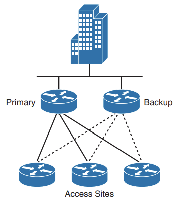
Since WAN links are often critical pieces of the internetwork, redundant media is often deployed in WAN environments through the use of backup links, which will only become active when a primary link goes down or becomes congested.
- Using floating static routes, can identify which route is the backup route through the specified administrative distance (used by Cisco routers to select which routing information to use).
- Backup links can be combined with load balancing and channel aggregation.
Fault Tolerance Link to heading
Security Link to heading
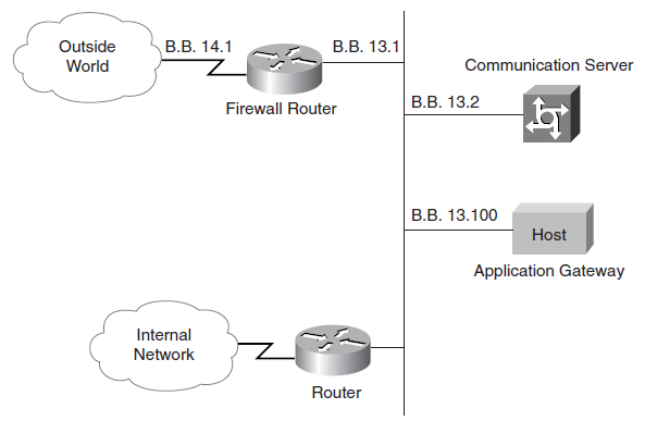
A firewall:
- Protects one network from another untrusted network.
- Provides stateful filtering of traffic, authenticates trusted remote sites, and provides connectivity using IPsec tunnels.
- Is a pair of mechanisms - One blocks traffic and the other permits traffic.
- Some firewalls place a greater emphasis on blocking traffic, and others emphasise permitting traffic.
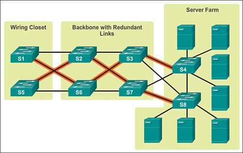
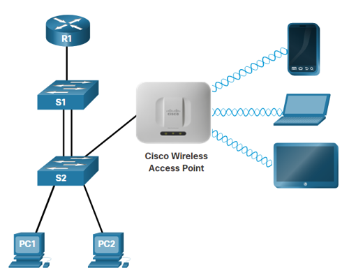
Reducing Failure Domain Size Link to heading
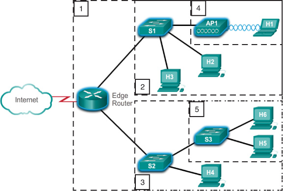
Considering the following failure domains:
- If the Edge Router fails, it will impact every device connected to it.
- If S1 fails, it will impact H1, H2, H3, and AP1.
- If S2 fails, it will impact S3, H4, H5, and H6.
- If AP1 fails, it will impact H1.
- If S3 fails, it will impact H5 and H6.
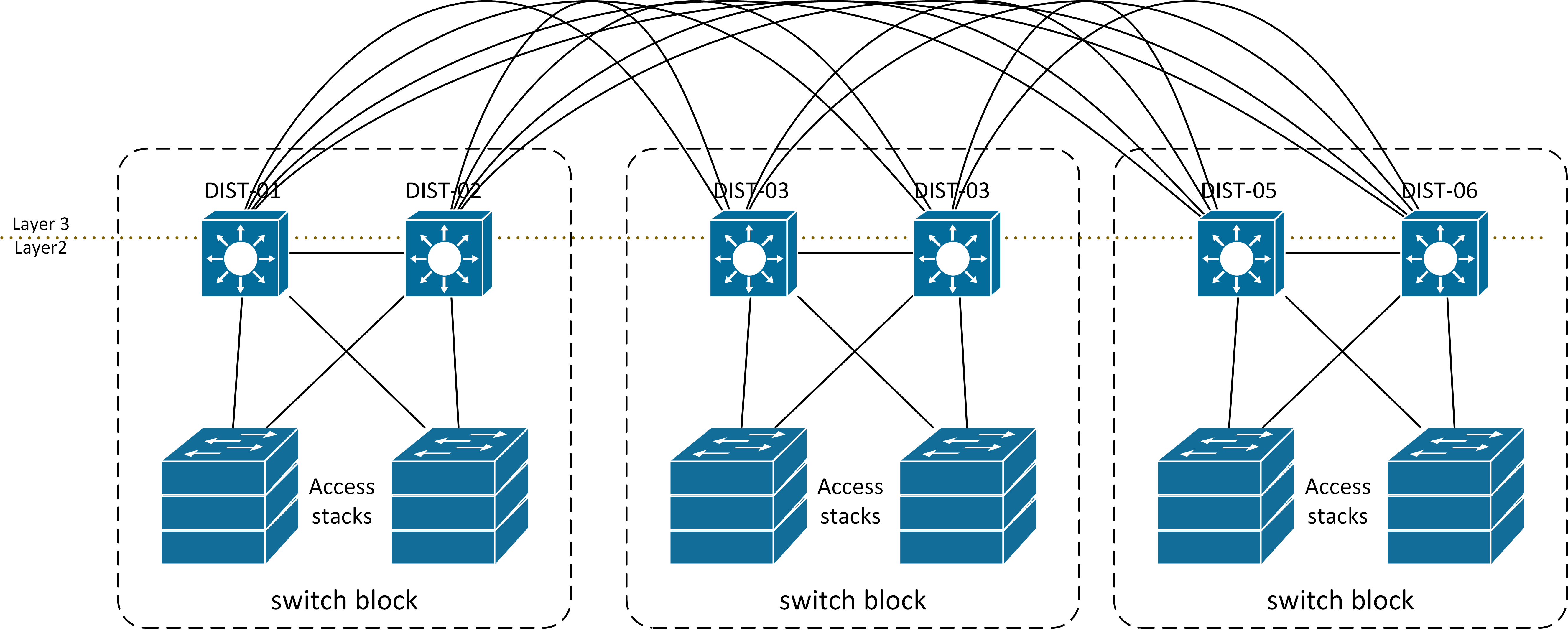
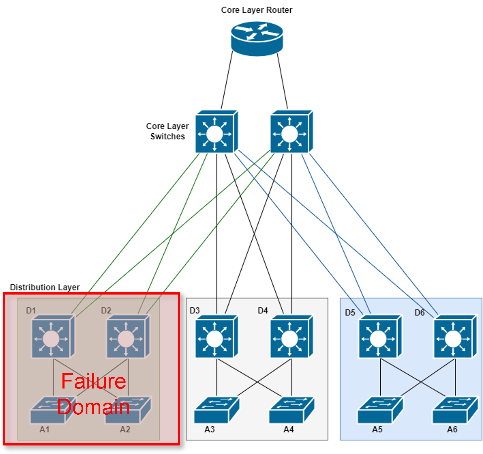
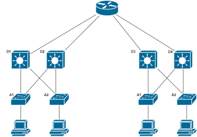
Routers, or multilayer switches, are usually deployed in pairs, with access layer switches evenly divided between them. This configuration is referred to as a building, or departmental, switch block.
- In the topology below, each switch block acts independently of the others.
- As a result, the failure of a single device does not cause the network to go down.
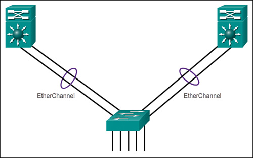
Link Aggregation Link to heading
- One technology used primarily on Cisco switches is EtherChannel.
- A Port Channel interface is the logical representation of the EtherChannel on the switch.
- Multiple Fast or Gigabit Ethernet links can be bundled into a single L2 or L3
logical link.
- However, L2 and L3 interfaces cannot be bundled into the same port channel.
- Port bundling can occur such that multiple interfaces share one logical address (i.e. IP) or one physical address (i.e. MAC address).
- Open-standard Link Aggregation Control Protocol (LACP) allows for up to 8 active ports
passing traffic and 8 ports on standby, whereas Cisco’s Port Aggregation
Protocol (PAgP) only allows for 8 active links.
- The switches involved in a LACP bundle negotiate a master/slave relationship and the designated master switch makes the decisions on which members are active and which are in “hot standby” mode when the number of members in the bundle exceeds 8.
- It is recommended to use the even number of ports in the channel to have better load balancing of traffic across these physical interfaces.
- Most configuration tasks are done on the port channel interface (instead of on each individual physical port) to ensure configuration consistency on the links.
- The port channel stays operational as long as at least one physical interface within the port channel is operational.
- Mode pairs:
- EtherChannels using LACP have two modes: Active and Passive. The following LACP mode combinations will result in a valid LACP port channel: active+active and active+passive.
- EtherChannels using PAgP have two modes: Desirable and Auto. The following LACP mode combinations will result in a valid LACP port channel: desirable+desirable and desirable+auto.
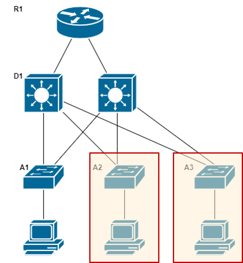
Expanding the Access Layer Link to heading
- A common option for extending Access layer connectivity is by a modular construction approach.
- Earlier, we defined the Switch Block as a construction unit or module. To expand the network, we base any new additions on this module.
- The benefits of this modular construction include:
- Easier to duplicate a design than starting from scratch
- Configuration is similar to pre-existing setup
- Performance would be similar
- Maintenance would be similar
- Design behaviour is predictable
- Familiarity makes troubleshooting easier
- An increasingly popular option for extending Access layer connectivity is through Wireless LANs (WLANs) which provides increased flexibility, reduced costs, and the ability to grow and adapt to changing network and business requirements.
- To communicate wirelessly, end devices require a wireless NIC to connect to a wireless router or a Wireless Access Point (AP).
- Considerations when implementing a wireless network include:
- Types of wireless devices connecting to the WLAN
- Wireless coverage requirements
- Interference considerations
- Security considerations
Expanding the Distribution Layer Link to heading
If the expansion is larger:
- The new switch block now includes the two redundant L3 switches.
- Configuration is still similar to the pre-existing setup.
- The Distribution Layer switches still connect to the two core routers.
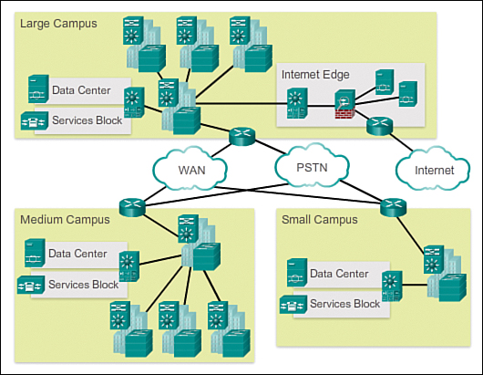
However, if the expansion is larger, as in the below example of multiple buildings on a campus.
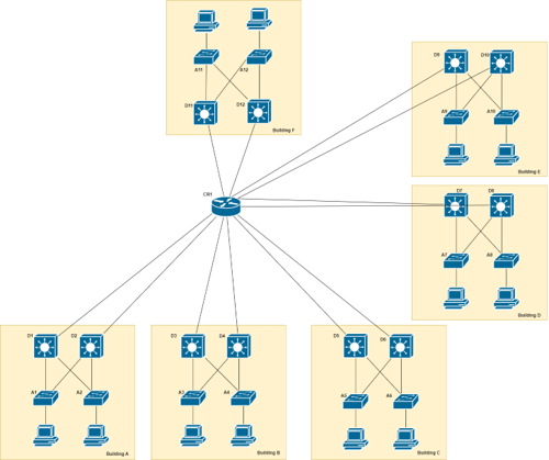
Thus, we need to expand the Core Layer to reduce the load on the Core router.
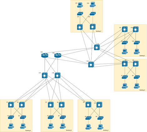
Expanding the Core Layer Link to heading
- Additional Core devices can spread the load and cope with the increased number of links.
- High throughput Multi-Layer Switches are a good use-case for this, due to their large number of available ports.
Fine-tuning Routing Protocols Link to heading
Enterprise networks and ISPs often use more advanced protocols, such as link-state protocols, because of their hierarchical design and ability to scale for large networks.
Link-state routing protocols, such as Open Shortest Path First (OSPF), work well for larger hierarchical networks, where fast convergence is important.
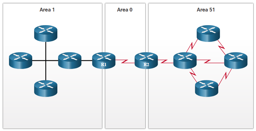
OSPF is a link-state routing protocol that uses the concept of Areas to support a hierarchical networks.
OSPF routers establish and maintain neighbour adjacencies with other connected OSPF routers.
OSPF routers synchronise their Link-State database.
When a network change occurs, Link-State updates are sent, informing other OSPF routers of the change and establishing a new best path, if one is available.
Campus Network Link to heading
Traditional campus network: High speed Layer 2 and Layer 3 Ethernet switching ports and routing interfaces connecting the End Users, the Data Centre and network services as well WAN resources.
Evolved campus network profile: The modern network is defined by being a collaborative, interactive and real-time communication environment for the End-user.
- Non-Stop High availability services to clients
- Access and Mobility services
- Application protection and Optimisation services
- Virtualisation services
- Security services
- Operational and Management services
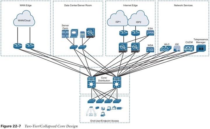
Enterprise Network Link to heading
Dedicated Network Areas Link to heading
Developments in network design have led to specialised sections or areas.
- For example: adding extra servers and locating them in a single area has led to the idea of a Server Farm.
- Data storage servers can be grouped into a Data Centre.
- The Internet Edge collects devices that manage and run Internet access and related services like security, via such devices as firewalls, proxy servers and DMZs.
- The WAN or Cloud Edge is dedicated to accessing services supplied by third parties.
- The Network Services sector looks after managing network devices, such as Wireless LAN Controllers (WLC) or Cisco’s Identity Services Engine (ISE), or Telepresence Manager, etc.
- These are the more specialised areas that are developed when the main network design is being planned.
- However, they may not be implemented right from the start – but when needed.
- Nevertheless, since they have been planned, expansion would not be problematic.