Table of Contents Link to heading
- Layer 2/3 Breakdown
- Access/Distribution Links
- Distribution/Core Links
- Virtual LANs (VLANs)
- Spanning Tree Protocol (STP)
- First-Hop Redundancy Protocols (FHRPs)
- FHRPs and STP Complications
- Multiple STP Topologies
- Alternative Approach to Access/Distribution Layers
- Routing
- Dynamic Routing
- Additional Considerations
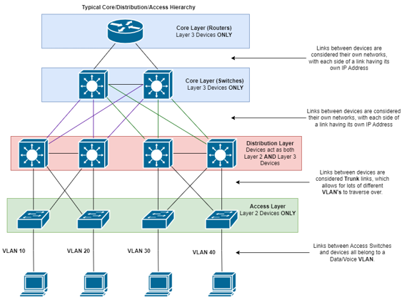
Layer 2/3 Breakdown Link to heading
- Each link between a Layer 3 (L3) device is considered its own network, with each side of the link having its own IP address.
- Access layer typically operates over Layer 2 (L2) only, separating ports into different VLANs.
- Access layer connects with Distribution layer via the use of trunk ports, which allows multiple different VLANs to traverse the Access/Distribution layer links.
- Distribution layer typically has a different network per VLAN.
Access/Distribution Links Link to heading
involve L2 communication, handling VLANs and Trunking.
- L2 communication is concerned with local traffic, managing data within a switch and its adjacent L2 switches.
- Access/Distribution links, aka trunk links, enable all VLAN traffic to traverse without routing, streamlining data transfer within network segments.
Distribution/Core Links Link to heading
focus on L3 communication, routing data between networks.
- L3 devices (routers, multilayer switches) use routing tables to determine optimal paths for data.
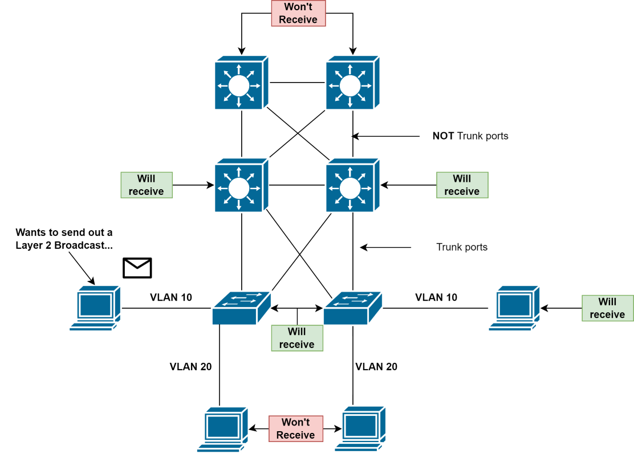
Virtual LANs (VLANs) Link to heading
segment L2 traffic into different broadcast domains.
- Traffic between VLANs are unable to directly contact each other between another L2 device.
- Broadcast traffic is limited to only the VLAN it originated from, as well as
trunk links (links between switches).
- Trunk links allow multiple VLANs to traverse over the same port. This is not relevant when only dealing with L3 traffic. As such, Core layer devices will not receive broadcasts as the link between a Distribution/Core link will be an L3 Port.
- Devices on different VLANs can still communicate with each other via the use
of Inter-VLAN routing.
- Inter-VLAN routing is implemented on the Distribution Layer devices, allowing the Distribution devices to operate across multiple VLANs.
- Devices connected to the Access layer use Distribution devices as middle-men when accessing devices on separate VLANs.
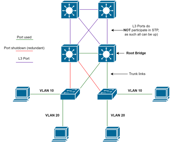
Spanning Tree Protocol (STP) Link to heading
removes redundant paths in a L2 topology, leaving only one logical path between all L2 devices.
- Required because a L2 Switch will forward broadcast frames through every trunk
port that is up.
- If all L2 Switches in the topology did this, and no ports were down, it would create a loop of broadcast traffic (referred to as a Broadcast storm).
- Logical path is determined by electing a Root Bridge, each switch then
calculates their best path to get to the Root Bridge.
- All other ports that are not being used to get to the root bridge (i.e. host device ports) are shut down.
- This only impacts L2 Ports (trunk links), not L3 Ports (links between
Distribution/Core switches).
- L3 deals with broadcast traffic on a per-network basis, and does not make use of trunking. As such, STP is not required.
First-Hop Redundancy Protocols (FHRPs) Link to heading
Info
FHRPs use a Virtual IP (VIP) and MAC address to allow for automated gateway
failover.
- Typically only one device can be the default gateway for a given network; however, there can be multiples with the use of FHRPs.
- Both devices share the same VIP and the hosts use the VIP as their default gateway address.
- One will be designated as the primary device which responds to all traffic, the other as the backup which will only respond to requests if the primary device goes down.
Examples of FHRPs:
- Hot Standby Router Protocol (HSRP): Cisco proprietary. Deployed in active/standby pair
- Virtual Router Redundancy Protocol (VRRP): Open standard. Deployed in active/standby pair. Very similar to HSRP.
- Gateway Load Balancing Protocol (GLBP): Cisco proprietary. Supports active/active load balancing across multiple routers.
FHRP is not a routing protocol as it does not advertise IP routes or affect the routing table in any way.
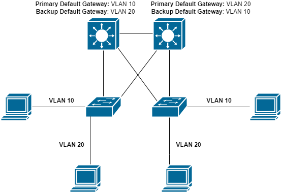
FHRPs and STP Complications Link to heading
- Due to the nature of STP, creating one logical path across all switches and removing redundant links, it makes using FHRPs to load-balance different complex networks.
- Traffic will likely have to go through the other multilayer switch to get to
their primary default gateway.
- This defeats the purpose of the load-balancing, as both devices are still being used.

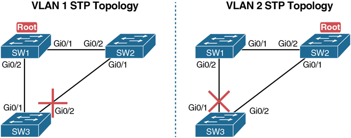
Multiple STP Topologies Link to heading
a solution to FHRPs and STP complications.
- You can have a different STP configuration per-VLAN.
- Changing the Root Bridge per-VLAN allows you to control what ports your traffic flows through to get to their Default Gateway.
- STP will reconfigure itself if a device goes down. You do not need to make considerations for if the primary device is down.
Alternative Approach to Access/Distribution Layers Link to heading
- In some circumstances, a network infrastructure will make use of multilayer switches in the Access layer.
- In this scenario, the Access layer’s multilayer switches act as the Default
Gateway rather than the Distribution layer.
- The ports connected to the host devices are still L2, and belong to a particular VLAN.
- This is used in networks where it is required to maximise the use of all
links, which cannot be done with Trunks/STP.
- Typically a Data Centre.
- Due to the lack of trunk links between the Access/Distribution devices, the
use of FHRPs is not applicable, other forms of redundancy are required.
- Access device typically traffic traverses across trunk links to get to the default gateways, but that is not possible when the Access Layer is the Default Gateway.
- Instead, access devices will typically have a direct link to multiple access switches.
- Lack of trunk links also means you cannot have a singular VLAN spanning
multiple Access switches.
- Devices on different Access switches are considered to be on different networks, and access to them has to be routed.
Routing Link to heading
- The Distribution/Core link facilitates routing traffic between various networks, connecting different Distribution Blocks or providing access to the Internet.
- The Distribution layer manages local routing within its Distribution block, while relying on the Core layer to direct traffic beyond its local network segment.
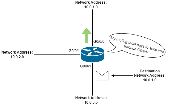
- L3 devices in the Distribution and Core layers maintain routing tables to
determine the best paths for networks.
- The routing table contains information like the Network Address, Exit Interface, and Next-Hop IP Address.
- L3 devices will load their directly connected networks into their routing
table, but rely on the cooperation of other L3 devices to build paths to other
networks.
- This process is referred to as Dynamic Routing. Static Routing is another solution, in which you hard-code network locations into the routing table, however this is used in specific use-cases only.
Dynamic Routing Link to heading
- Core/Distribution devices use Dynamic Routing Protocols to learn about
networks associated with other L3 devices.
- Common protocols include OSPF, EIGRP, and RIP.
- These devices create a “topology” that maps out other L3 devices, their
networks, and connections, helping to determine the best path to specific
networks.
- Paths to a network are given a cost, the path with the lowest cost is chosen as the preferred path to the network.
- In cases where paths have equal costs, the router can load balance traffic between the two paths, without the need for any additional routing protocol.
Additional Considerations Link to heading
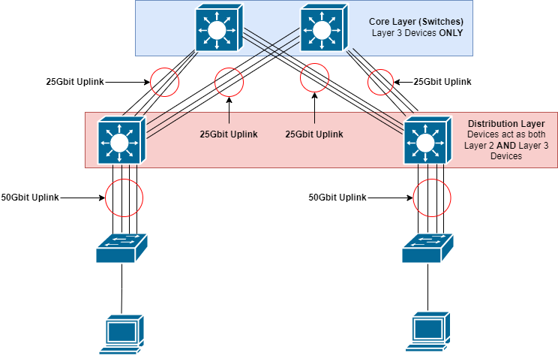
- Consider bandwidth usage on Access layer devices.
- Example: 48x1Gbit Port Switch at Access layer has 48Gbit total switching capacity.
- Links between Access and Distribution layers should handle the entire
throughput of the downstream Access devices.
- This also applies for Distribution -> Core uplinks.
- Core Switch -> Core Router uplinks do not need to facilitate this, as your
Internet speed will likely not match your max network throughput.
- Matching max throughput between Access/Distribution/Core switches should be done to ensure all internal traffic flow is adequate.
- Combine multiple links if a single uplink is insufficient. If there is multiple devices to uplink to, you can split the throughput between them.