
Table of Contents Link to heading
- Flat Model
- Hierarchical Model
- Three-layered model
- Access Layer
- Distribution Layer
- Core Layer
- Two-layered Model
- Access Switches versus Distribution Switches
- Role of Switched Networks
- Evolution of Switched to Routed Network Links
- Summary
Flat Model Link to heading
All devices are connected to a single switch instead of separate ones.
- Provides little opportunity to control broadcasts or to filter undesirable traffic.
- As more devices and applications are added to a flat network, response times degraded, making the network unusable.
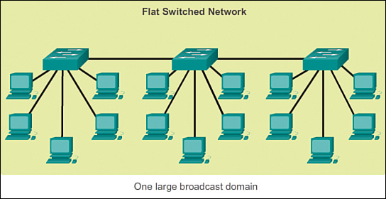
Image Source: GitBook
Hierarchical Model Link to heading
The network is divided into distinct layers/tiers, each of which provides specific functions that define its role within the overall network.
- Akin to the purpose of the OSI model, layers are used to simplify the tasks required for internetworking.
- This helps the network designer and architect to optimise and select the right network hardware, software, and features to perform specific roles for that network layer.
- Hierarchical models apply to both LAN and WAN design.
- Implementing hierarchical models has many benefits:
- Cost savings: enable appropriate use of bandwidth within each layer of the hierarchy, reducing wasted capacity.
- Ease of understanding: keep each design element simple and small.
- Easy network growth: modularity allows creating design elements that can be replicated as the network scales whilst minimising impacts on other elements.
- Improved fault isolation: network managers can easily understand the transition points in the network, which helps identify failure points.
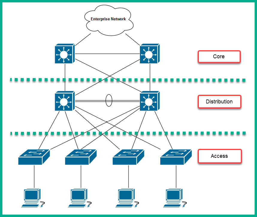
Image Source: Packt
Three-layered model Link to heading
The time-tested and proven hierarchical design frameworks for campus networks is the three-layered model. It helps you design, implement, and maintain a scalable and reliable network.
Access Layer Link to heading
provides user access to local segments on the network.
- In campus environments, the Access layer generally incorporates L2 switches and Access Points to provide connectivity, high bandwidth between workstations and servers.
- In small office/home office (SOHO) environments, the Access layer provides access for remote sites into the corporate network by using WAN technologies (such as ISDN, Frame Relay, and leased lines). Other features, such as dial-on-demand routing (DDR) and static routing, can be implemented to control costs.
Functions of the Access layer include the following:
- Layer 2 switching
- Bandwidth LANs sharing
- Collision domains on Ethernet segments division
- High availability
- Port security
- Broadcast suppression
- QoS classification and marking and trust boundaries
- Rate limiting/policing
- Address Resolution Protocol (ARP) inspection
- Virtual access control lists (VACLs)
- Spanning tree
- Trust classification
- Power over Ethernet (PoE) and auxiliary VLANs for VoIP
- Network Access Control (NAC)
Design Best Practices Link to heading
- Limit VLANs to a single closet when possible to provide the most deterministic and highly available topology.
- Use RPVST+ if STP is required. It provides the best convergence.
- Set trunks to ON and ON with no-negotiate.
- Manually prune unused VLANs to avoid broadcast propagation.
- Use VTP Transparent mode, because there is little need for a common VLAN database in hierarchical networks.
- Disable trunking on host ports, because it is not necessary. Doing so provides more security and speeds up PortFast.
- Consider implementing routing in the access layer to provide fast convergence and L3 load balancing.
- Use Cisco STP Toolkit, which provides PortFast, Loop Guard, Root Guard, and BPDU Guard.
Distribution Layer Link to heading
aggregates the data received from the Access layer switches before transmitting them to the Core layer for routing to its final destination.
The distribution layer can have many roles, including implementing the following functions:
- Policy-based connectivity (e.g. ensuring that traffic sent from a particular network is forwarded out one interface while all other traffic is forwarded out another interface)
- Redundancy and load balancing (e.g. FHRP definition)
- Aggregation of LAN wiring closets
- Aggregation of WAN connections
- Address or area aggregation
- QoS
- Security filtering
- Departmental or workgroup access
- Media translations (e.g. between Ethernet and Token Ring)
- Broadcast or multicast domain definition
- Inter-VLAN routing
- Demarcation between static and dynamic routing
- Redistribution between routing domains (e.g. between two different routing protocols)
Several Cisco IOS software features can be used to implement policy at the Distribution layer:
- Filtering by source or destination address
- Filtering on input or output ports
- Hiding internal network numbers by route filtering
- Static routing
- QoS mechanisms (e.g. ensuring that all devices along a path can accommodate the requested parameters)
Design Best Practices Link to heading
- Use first-hop redundancy protocols (FHRP).
- Hot Standby Router Protocol (HSRP) or Gateway Load Balancing Protocol (GLBP) should be used if you implement L2 links between the access and distribution.
- Use L3 links between the distribution and core switches to allow for fast convergence and load balancing.
- Build L3 triangles, not squares.
- Use the distribution switches to connect L2 VLANs that span multiple access layer switches.
- Summarise routes from the distribution to the core of the network to reduce routing overhead.
- Use VSS as an option to eliminate the use of STP.
Core Layer Link to heading
high-speed switching backbone of the network that is crucial to enable corporate communications.
Usually consists of high speed devices, like high end routers and switches with redundant links.
The core layer should have the following characteristics:
- Fast transport
- High reliability
- Redundancy
- Fault tolerance
- QoS
- Low latency and good manageability
- Avoidance of CPU-intensive packet manipulation caused by security, inspection, QoS classification, or other processes
- Limited and consistent diameter - same number of hops from any end station to
another end station across the backbone.
- Distribution layer routers and client LANs can be added to the hierarchical model without increasing the diameter because neither will affect how existing end stations communicate.
Design Best Practices Link to heading
- Reduce the switch peering by using redundant triangle connections between switches.
- Use routing that provides a topology with no spanning-tree loops.
- Use L3 switches on the core that provide intelligent services that L2 switches do not support.
- Use two equal-cost paths to every destination network.
Two-layered Model Link to heading
or Collapsed-Core model, where the Core and Distribution layers are merged, providing all the services needed for those layers.
- Greatly reduces network cost, given fewer L3 networking devices.
- Commonly used on sites with a single building with just multiple floors.
- Might also be implemented in larger networks when the Core/Distribution equipment is so sophisticated or when separate Core and Distribution layers are not a need.
- Migrate to the three-layer model if the network suffers from:
- Inadequate capacity and throughput at the Distribution layer
- Network resiliency
- Geographic dispersion
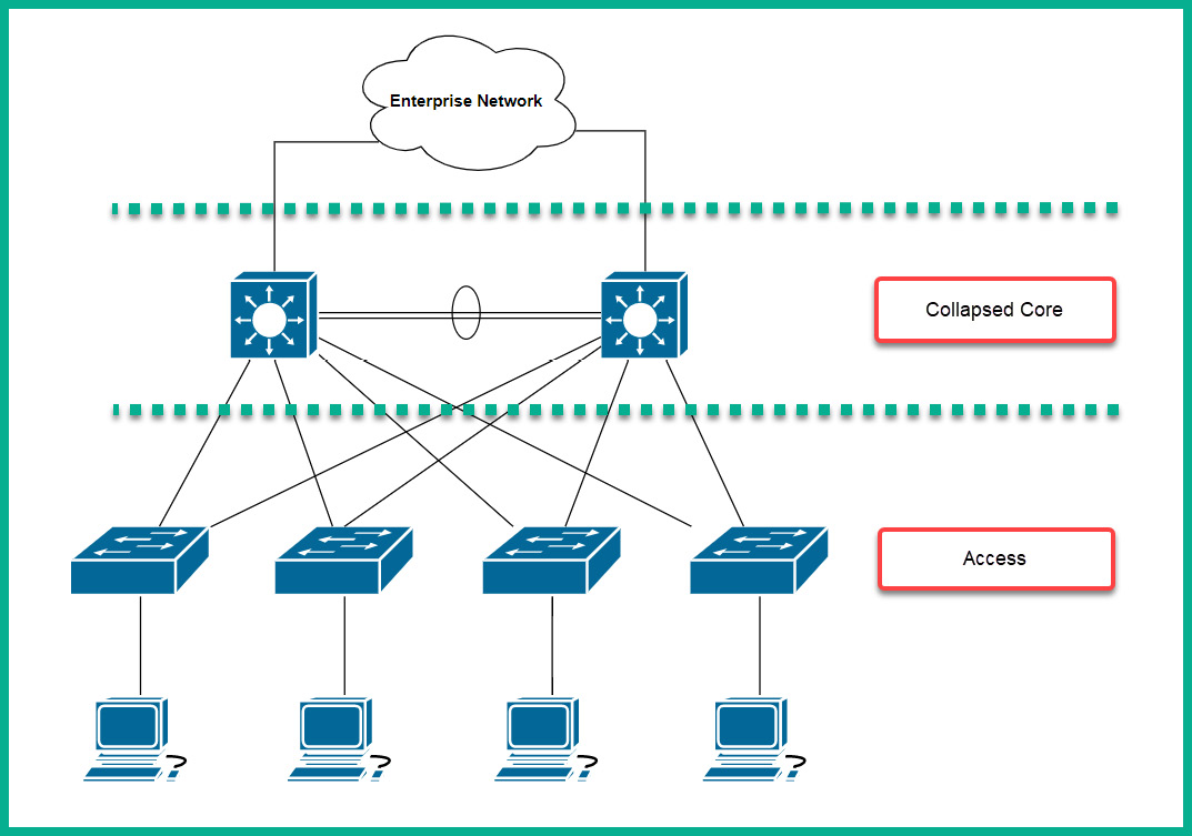
Image Source: Packt
Access Switches versus Distribution Switches Link to heading
| Switch Type | Description |
|---|---|
| Access Switch | Connect to endpoint devices |
| Distribution Switch | Connect to each access switch, providing a means to distribute frames throughout the LAN |
Role of Switched Networks Link to heading
- Networks have fundamentally changed from a flat network of hubs, to a hierarchical network of switches.
- A switched LAN allows additional flexibility, traffic management, quality of service, and security.
- A switched LAN may also support wireless networking and other technologies, such as IP phones and mobility services.
Evolution of Switched to Routed Network Links Link to heading
- In earlier times, networks mainly consisted of switches since routers were relatively slower.
- Thus, links were mainly L2.
- As routing processes and router hardware evolved, router speeds improved greatly.
- While L2 switching still runs at the Access layer, L3 links began to trickle down the network hierarchy.
- This was helped by the invention of the L3 switch or multilayer switch.
Summary Link to heading
| Layer | Description |
|---|---|
| Access layer | The entry points to the network, as seen by the end user |
| Distribution layer | Policy-based connectivity, aggregation of the many Access layer links, representing the network users into paths leading to local (servers) or remote (Internet) resources |
| Core layer | High-speed connection and optimal transport between sites |