Table of Contents Link to heading
- Switching Basics
- Routing versus Switching
- Types of Switches
- Network Domains
- Duplex and Bandwidth/Speed Settings
- Auto-MDIX
- Switch Boot Sequence
- Switch LED Indicators
- Accessing the Boot Loader CLI (After a System Crash)
- Switch Form Factors
- Business Considerations for Switch Selection
- Switch Management
Switching Basics Link to heading
A switch:
- never allows traffic to be forwarded out the interface it received the traffic on.
- knows where to forward a frame based on the ingress interface and the destination MAC address.
- uses its MAC address table to determine where to send frames.
- must learn what the MAC addresses are on its interfaces by looking at the
frames travelling through it to identify what source MAC address is at what
interface.
- These MAC addresses are stored in the content-addressable memory (CAM) table (or the MAC address table).
The following two videos gives a general explanation of how a switch forwards and builds the MAC address table:
Frame Forwarding Decision Link to heading
Frame Forwarding Mechanisms Link to heading
Routing versus Switching Link to heading
Routing (Layer 3)
- Helps traffic get from source to a destination outside of their current network.
- Makes use of an IP Address to identify a device, with the IP Address belonging to a larger network.
- Networks mapped to a routing table.
- Can go to networks outside of the routers’ local proximity through the use of a default gateway - will forward all traffic it does not know what to do with to there.
Switching (Layer 2)
- Helps traffic get from source to a destination within their current broadcast domain.
- Makes use of a MAC Address to identify a device, with the MAC Address belonging to a larger broadcast domain.
- Will only operate within its current broadcast domain. As a result, it does not care about locations not in its local proximity.
Types of Switches Link to heading
Managed Switches Link to heading
Unmanaged Switches Link to heading
L3/Multilayer Switches Link to heading
Network Domains Link to heading
Collision Domains Link to heading
- The packets collide and both devices must send the packets again, which reduces network efficiency.
- Repeaters and hubs suffer from issues with collision domains because each port on a hub is in the same collision domain.
- Switches, bridges, and routers mitigate this by placing each port in its own collision domain.
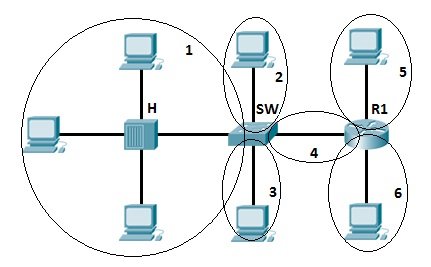
Broadcast Domains Link to heading
- Broadcast domains typically are bounded by routers or by VLANs (in a switched network).
- Switches forward broadcast frames to all ports, except the incoming port.
- Since all ports on a switch are by default in the same broadcast domain.
- Routers do not forward broadcast frames from one broadcast domain to another.
- Since all ports on a router are by default in different broadcast domains.
- Switches do not, by default, break broadcast domains, except for the implementation of VLANs.
In the following illustration, there are three broadcast domains.
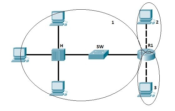
Image Source: Study CCNA
Duplex and Bandwidth/Speed Settings Link to heading
It is critical that the duplex and bandwidth settings match between the switch port and the connected devices.
- Half-duplex: only one end of the connection can send at a time.
- After one device has done sending its data, the other one can receive.
- Full-duplex: both ends of the connection can send and receive
simultaneously.
- Gigabit Ethernet ports operate only in full-duplex.
- Preferred if both devices have the capability, along with their highest common bandwidth.
- Best practice to avoid duplex mismatch.
Autonegotiation Link to heading
Most Cisco switches and Ethernet NICs default to autonegotiation for speed and duplexing.
For example, PC-A is connected to a switch S1.
- The Ethernet NIC for PC-A can operate in full-duplex or half-duplex and at 10 Mbps or 100 Mbps.
- S1 can operate in full-duplex or half-duplex and at 10 Mbps, 100 Mbps, or 1000 Mbps (1 Gbps).
- If both devices are using autonegotiation, the operating mode is full-duplex, at 100 Mbps.
Duplex Mismatch Link to heading
Duplex mismatch may be caused by:
- Two interfaces are manually set at different duplex modes.
- Autonegotiation is enabled on one side of a link and the other is manually set to a full duplex mode.
- One or both interfaces on a link are reset, and the autonegotiation process does not result in the two link partners having the same configuration.
- Users reconfigure one side of a link and forget to reconfigure the other.
Both sides of a link should have autonegotiation on, or both sides should have it off.
In the following scenario, S2 will continually experience collisions because S1 keeps sending frames even when it has something to send.
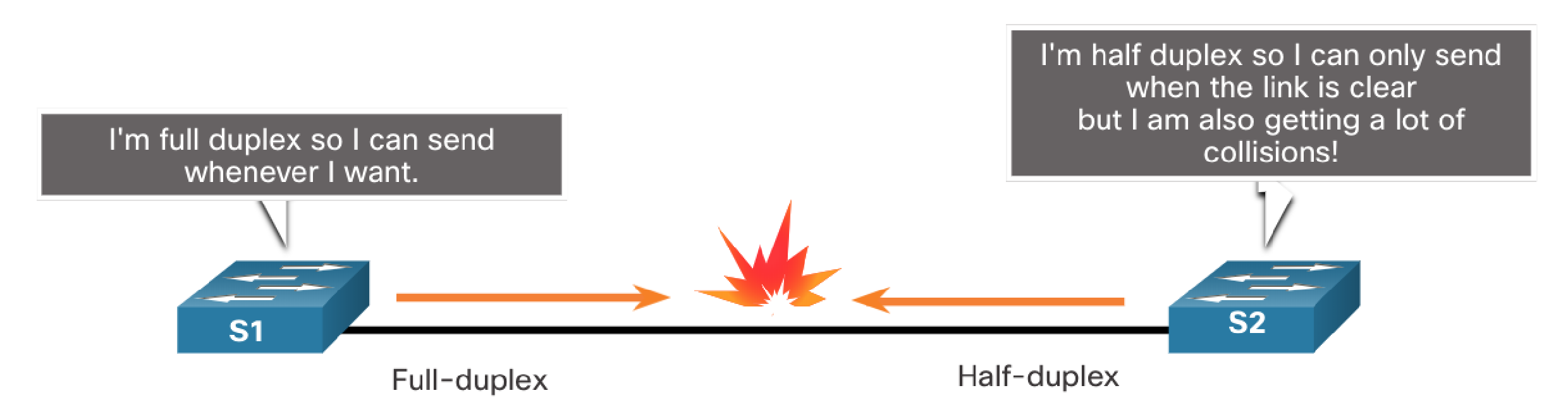
To set the duplex mode to full on both sides (which disables the default autonegotiation setting):
S1(config)# int g0/1
S1(config-if)# duplex full
S2(config)# int g0/2
S2(config-if)# duplex full
Auto-MDIX Link to heading
Switch Boot Sequence Link to heading
- Switch loads a power-on self-test (POST) program stored in ROM, POST checks the CPU, DRAM and the portion of the flash device that makes up the flash filesystem structure.
- Loads boot loader software. The boot loader is stored in ROM that is run immediately after a successful POST.
- Boot loader performs low-level CPU initialisation (registers) which control where physical memory is mapped and the quantity and speed of memory.
- Boot loader initialises the flash filesystem on the system board.
- Boot loader locates (from the BOOT variable) and loads a default IOS operating system software image into memory and gives control of the switch to the IOS.
- In the case when the BOOT environment variable is not set, the switch will attempt to load the first executable file it can find on the flash.
- The IOS operating system will initialise the interfaces using the commands found in the startup-config. The startup-config file is named differently on the flash: config.text.
- You can change the boot environment variable using the boot system command. This is useful when booting a specific IOS version, or booting from an alternative device (USB).
boot system path_to_fileis the global configuration command to change the environment variable.
Switch LED Indicators Link to heading
Switches have a variety of indicators on both the ports and on the side near the mode button.
- System (SYST): Whether the system is receiving power and functioning properly.
- Redundant Power Supply (RPS): Shows the RPS status.
- Port Status (STAT): Green indicates port status mode is selected, which is the default. Status can then be understood by the light associated with each port.
- Port Duplex (DUPLX): Green indicates port duplex mode is selected. Duplex can then be understood by the light associated with each port.
- Port Speed (SPEED): Exactly the same as DUPLX except for speed instead.
- Power over Ethernet (PoE): Present if the switch supports PoE. Indicates the PoE status of ports on the switch.
- The Mode button is used to move between STAT, DUPLX, SPEED and PoE, changing the port LED meaning.
Accessing the Boot Loader CLI (After a System Crash) Link to heading
The boot loader CLI provides access to the files stored on the flash memory and has many useful commands to format, reinstall an operating system, recover passwords and more.
Perform the following steps to access the boot loader CLI:
- Connect a computer to the switch console port. Ensure terminal emulation software (PuTTy, TeraTerm) is ready.
- Unplug the switch power cord (most switches do not have power switches on them).
- Reconnect the power cord to the switch and within 15 seconds press and hold down the Mode button while the SYS LED is still flashing green.
- Continue pressing the Mode button until the SYS LED turns briefly amber and then solid green. Release the Mode button.
- In your terminal emulation software you should see the switch: prompt.
Switch Form Factors Link to heading
Business Considerations for Switch Selection Link to heading
Switch Management Link to heading
Preparing for Basic Switch Management Link to heading
- Remote management of a switch must be manually configured.
- IP address and subnet mask must be configured on the SVI.
- If management occurs from a remote network (the Internet), a default gateway must be configured.
- Layer 2 switches can have an IP address and default gateway but will not route Layer 3 packets.
Managing Devices via Secure Shell (SSH) Link to heading
- Very common on UNIX-based systems.
- Certain IOS software features (cryptography) are required to enable SSH on switches.
- SSH uses TCP port 22 by default. Telnet uses TCP port 23.
- Telnet, which is insecure and not encrypted, should never be used for management connections.
Requires the following to be configured for it to work correctly:
- An IP domain name set
R1(config)# ip domain-name tanducmai.com
- A user account created
R1(config)# username tanducmai password henrymai
- An RSA cryptography key generated
R1(config)crypto key generate rsaHow many bits in the modulus [512]: 1024;- The more bits you have the longer the key and harder to crack.
- Cisco documentation likes 1024.
- Input method set to SSH only on all VTY lines
R1(config)# line vty 0 15R1(config-line)# transport input ssh- [Optional] Synchronise message output
R1(config-line)# logging synchronous
- [Optional] Enable the display of the MOTD banner
R1(config-line)# motd-banner
For example, to connect a PC (192.168.1.2) to R1 (192.168.1.1).
PC# telnet 192.168.1.1orPC# ssh 192.168.1.1- It will then authenticate user access by prompting for the username and the password created previously.