Table of Contents Link to heading
- Spanning Tree Versions
- Spanning Tree Protocol (STP)
- Spanning-Tree Algorithm (STA)
- Port Cost
- STP Port States
- STP Port Types
- STP Convergence
- STP Timers
- STP Topology Changes
- Per-VLAN Spanning Tree Plus (PVST+)
- Rapid Spanning Tree Protocol (RSTP)
- Multiple Spanning Tree (MST)
- Configuring and Verifying BID
- Cisco STP Toolkit
- Troubleshooting STP
Spanning Tree Versions Link to heading
- 802.1D – original specification
- Good for learning, a single spanning tree is used.
- Often called Common Spanning Tree (CST) and STP.
- Per-VLAN Spanning Tree (PVST)
- Uses the Cisco proprietary ISL trunking protocol.
- Inter-Switch Link (ISL) – a way of tagging like 802.1Q.
- Each VLAN has an instance of spanning tree.
- Ability to load balance traffic at L2.
- Includes extensions BackboneFast, UplinkFast, and PortFast.
- Uses the Cisco proprietary ISL trunking protocol.
- Per-VLAN Spanning Tree Plus (PVST+)
- Supports ISL and IEEE 802.1Q trunking.
- Supports Cisco proprietary STP extensions.
- Adds BPDU guard and root guard enhancements.
- Root switch selection is done for each VLAN.
- Generally unusable in mixed vendor environments.
- 802.1W Rapid Per-VLAN Spanning Tree Plus (RPVST+)
- Has faster convergence than 802.1D.
- Root switch selection is done for each VLAN.
- Use RPVST+ if STP is required since it provides for faster convergence than traditional 802.1D default timers.
- 802.1W Rapid Spanning Tree Protocol (RSTP)
- Introduced in 1982 and provides faster convergence than 802.1D.
- The replacement for CST/STP (IEEE 802.1D), which also provides backwards compatibility.
- Implements generic versions of the Cisco-proprietary STP extensions.
- IEEE has incorporated RSTP into 802.1D, identifying the specification as IEEE 802.1D-2004.
- 802.1S Multiple Spanning Tree (MST)
- Inspired by the Cisco’s Multiple Instances Spanning Tree Protocol (MISTP).
- IEEE 802.1Q (2003) now includes MST.
- Multiple VLANs can be mapped to the same spanning-tree instance.
- Root switch selection is based on instances.
- Generally unusable in mixed vendor environments.
| Name | Based on STP or RSTP? | # Trees | Original IEEE Standard | Config Parameter |
|---|---|---|---|---|
| STP | STP | 1 (CST) | 802.1D | N/A |
| PVST+ | STP | 1/VLAN | 802.1D | pvst |
| RSTP | RSTP | 1 (CST) | 802.1w | N/A |
| Rapid PVST+ | RSTP | 1/VLAN | 802.1w | rapid-pvst |
| MSTP | RSTP | 1 or more* | 802.1s | mst |
Spanning Tree Protocol (STP) Link to heading
Without STP, redundancy in the switched network, albeit useful for network reliability, would introduce the following LAN issues:
| Problem | Description |
|---|---|
| Broadcast storms | Each switch floods broadcasts endlessly. |
| Multiple frame transmission | Multiple copies of one frame are delivered to the intended host, confusing the host. |
| MAC database instability | Incorrect entries in the MAC address table result from copies of the same frame being received on different ports of the switch. |
Since L2 does not have a “Time To Live” field like L3, the frame will never be discarded if there is a physical or logical loop in a network.
STP creates a spanning tree of interfaces that forward frames. The tree structure of forwarding interfaces creates a single path to and from each Ethernet link.
Switches exchange messages to detect loops (which are removed by shutting down selected switch ports), preventing frames from circling the network forever.
If any network segment experiences a disruption in connectivity, STP rebuilds a new tree by activating (unblocking) the previously inactive, but redundant, path.
Spanning-Tree Algorithm (STA) Link to heading
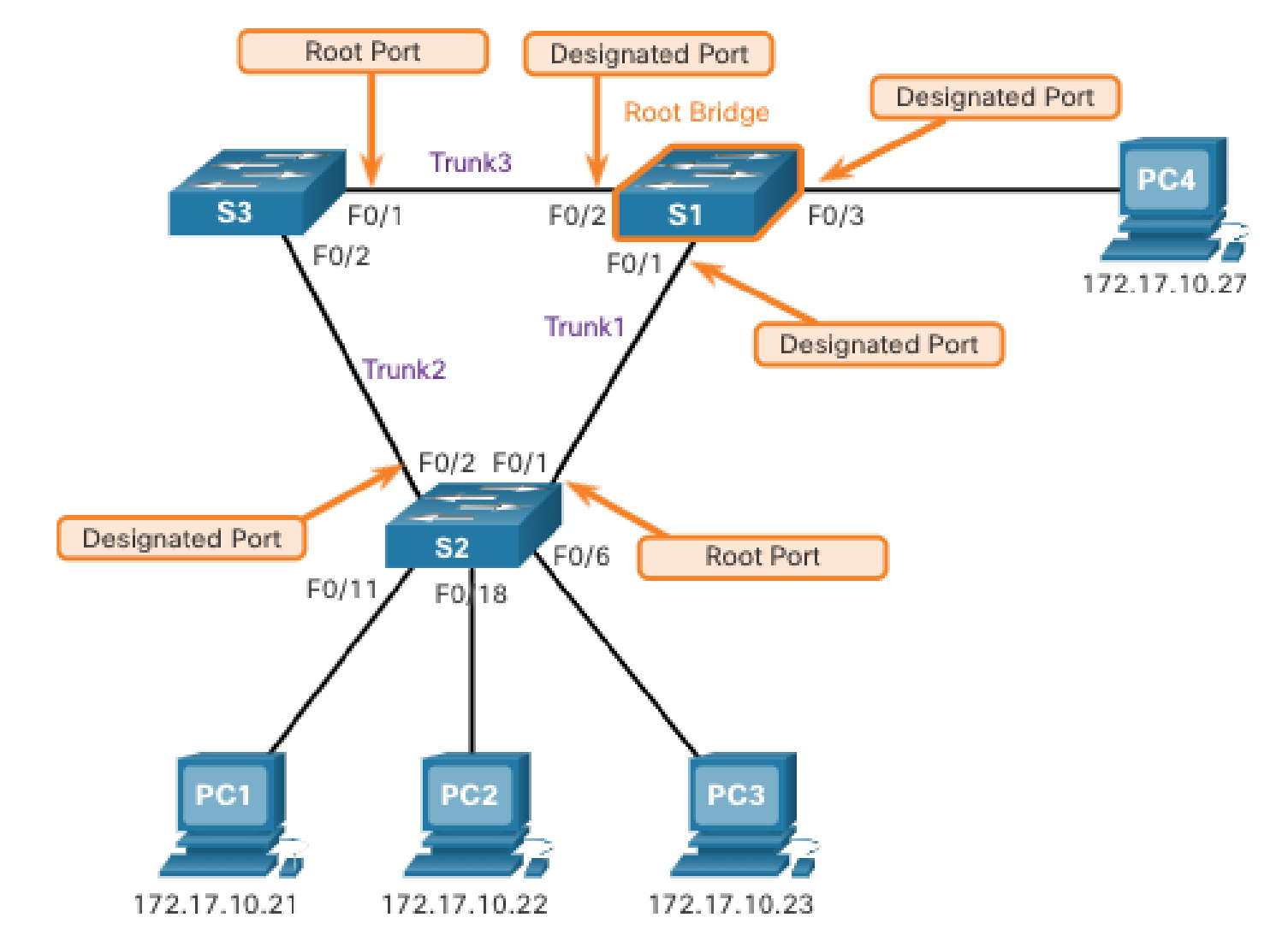
- A single switch is designated as the root switch and is used as the reference
point for all subsequent calculations.
Root Switch/Bridgeis the upstream switch, all of whose active interfaces are in a forwarding state and are categorised as a Designated Port.- STP was created before LAN switches even existed, using LAN bridges to connect LANs. Since nowadays switches play the same role as bridges, the term bridge and switch is used synonymously in terms of STP.
- Spanning Tree Algorithm (STA) is how STP chooses the forwarding interfaces that should be placed into a forwarding state.
- A Bridge Protocol Data Unit (BPDU) or configuration BPDUs is a frame
containing STP information exchanged by switches using STP.
- The most common BPDU is a Hello BPDU which contains:
- Root BID - The BID of the sender of this Hello, currently believed to be the root switch.
- Sender’s BID - The BID of the switch sending this Hello BPDU.
- Sender’s root cost - The root cost between this switch and the current root.
- Timer values on the root switch - Includes the Hello timer, MaxAge timer, and forward delay timer.
- The root switch sends periodic Hello BPDUs (default, 2 seconds).
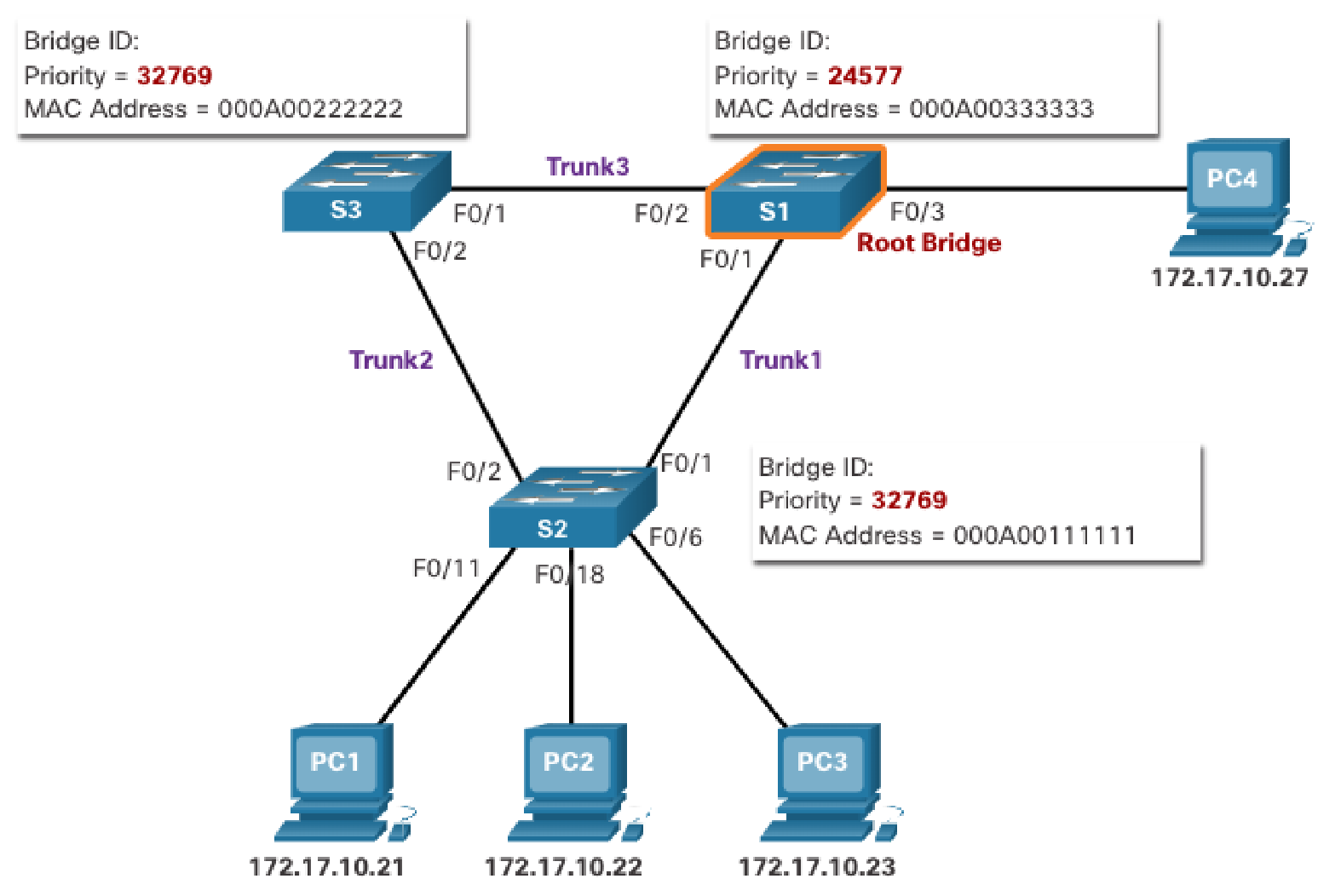
- Each configuration BPDU contains a bridge ID (BID) that identifies the
switch that sent the BPDU. The switch with the lowest BID becomes the root
switch.
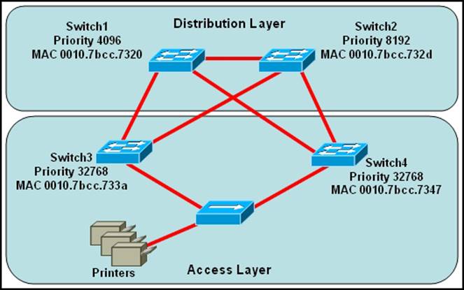
- Bridge ID (BID) - an 8-byte value unique to each switch: 2-byte
priority field and 6-byte system ID (burned-in address) .
- Priority - [configurable] - increments in blocks of 4096, from 0 up to 61440 (default, 32768).
- System ID - [blocks of unconfigurable] - unique amongst all switches, ensuring a unique BID.
- Extended System ID - a 12-bit field borrowed from the priority field to identify the VLAN ID held in this BPDU.
- Bridge ID (BID) - an 8-byte value unique to each switch: 2-byte
priority field and 6-byte system ID (burned-in address) .
- The most common BPDU is a Hello BPDU which contains:
- Root election process - The root switch with the lowest bridge priority or
(if that ties) the lowest numerical MAC address becomes the root bridge.
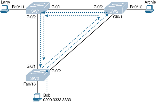
- The process begins with all switches claiming to be the root by sending Hello BPDUs listing their own BID as the root BID. If a switch hears a Hello that lists a better (lower) BID, it stops advertising itself as root and starts forwarding the superior Hello.
- You can manually lower the bridge priority value of the switch that you want to be the STP root.
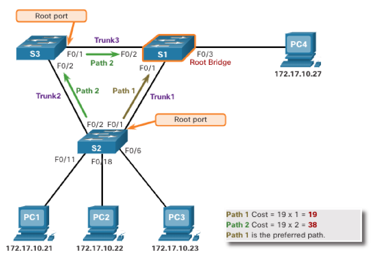
- After the root switch has been determined, for every nonroot switch, the STA
elects its root port by calculating the shortest path to the root switch,
which is the path with the least-cost path.
Root Port (RP)is the port closest to the root switch and is in a forwarding state.- There should only be one root port per VLAN on a switch.
- The root cost is the sum of all STP costs for all ports out which a
frame will exit if it flows over that path to reach the root.
- When a switch receives a BPDU, it adds the ingress port cost of the segment to determine its internal root path cost.
- If a switch has multiple equal-cost paths to the root switch, the
switch will determine a port using the following tiebreakers, in
order:
- The lowest BID
- The lowest interface STP priority (default, 128)
- The lowest internal interface number (e.g., F0/1, F0/2, F0/3)
- Default port costs can be found at 🔗. These can be changed manually per port.
- The last two tiebreakers are unlikely today, used when a single switch can connect two or more interfaces to the same collision domain by connecting to a hub. In that case, the one switch hears its own BPDUs.
- After all switches have their root ports elected, the other switch ports are then configured into different port roles. The port roles describe their relation in the network to the root switch and whether they are allowed to forward traffic.
Designated Port (DP)– an active port that is in a forwarding state and thus permitted to receive and forward BPDU frames to other switches.- DPs provide connectivity to downstream devices and switches.
- There should be only one active DP on a link to another switch.
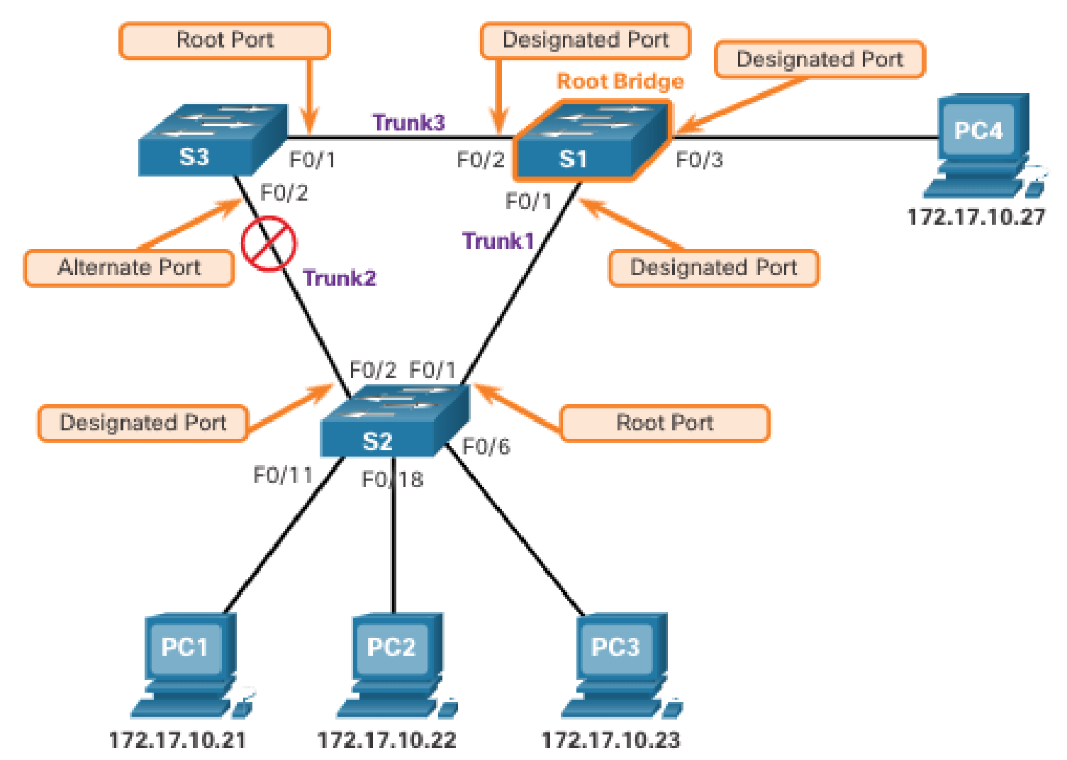
Non-Designated Port- an active port that is blocked from forwarding traffic due to STP calculations.- Non-designated ports are neither a RP or a DP.
Step 1 - Electing Root Switch Link to heading
The first step with STP is to identify the root switch. As a switch initialises, it assumes that it is the root switch and uses the local bridge identifier as the root switch identifier.
It then listens to its neighbour’s configuration BPDU and does the following:
- If the neighbour’s configuration BPDU is inferior to its own BPDU, the switch ignores that BPDU.
- If the neighbour’s configuration BPDU is preferred to its own BPDU, the switch updates its BPDUs to include the new root switch identifier along with a new root path cost that correlates to the total path cost to reach the new root bridge.
- This process continues until all switches in a topology have identified the root switch.
- STP prefers lower priority number then goes to lower MAC address.
Step 2 - Electing Root Ports Link to heading
Once the Root Switch is found, the switch must determine its Root Port. The RP is selected using the following logic:
- The interface associated to lowest path cost is more preferred.
- The interface associated to the lowest system priority of the advertising switch is preferred next.
- The interface associated to the lowest system MAC address of the advertising switch is preferred next.
- When multiple links are associated to the same switch, the lowest port priority from the advertising switch is preferred.
- When multiple links are associated to the same switch, the lower port number from the advertising switch is preferred.
Step 3 - Electing Designated Ports Link to heading
Step 4 - Electing Non-Designated Ports Link to heading
The RPs have been identified and all other ports are considered designated ports. If two non-root switches are connected to each other on their designated ports, one port must be set to a blocking state to prevent a forwarding loop.
Calculate which ports should be blocked between two non-root switches:
- The interface is a designated port and must not be considered an RP.
- The switch with the lower path cost to the root switch forwards, and the one with the higher path cost blocks. If they tie, they move on to the next step.
- The system priority of the local switch is compared to the system priority of the remote switch. The local port is moved to a blocking state if the remote system priority is lower than that of the local switch. If they tie, they move on to the next step.
- The system MAC address of the local switch is compared to the system priority of the remote switch. The local designated port is moved to a blocking state if the remote system MAC address is lower than that of the local switch. If the links are connected to the same switch, they move on to the next step.
Port Cost Link to heading
| Link Speed | IEEE 802.1D Standard (Short-mode) | Latest IEEE Standard (Long-mode) |
|---|---|---|
| 10 Mbps | 100 | 2,000,000 |
| 100 Mbps | 19 | 200,000 |
| 1 Gbps | 4 | 20,000 |
| 10 Gbps | 2 | 2,000 |
| 20 Gbps | 1 | 1,000 |
| 100 Gbps | N/A | 200 |
| 1 Tbps | N/A | 20 |
| 10 Tbps | N/A | 2 |
- The interface STP cost was originally stored as a 16-bit value, called short
mode, with a reference value of 20 Gbps.
- This is the default mode.
- Another method, called long mode, uses a 32-bit value and uses a reference speed of 20 Tbps.
Switch(config)# spanning-tree pathcost method <long / short>
STP Port States Link to heading
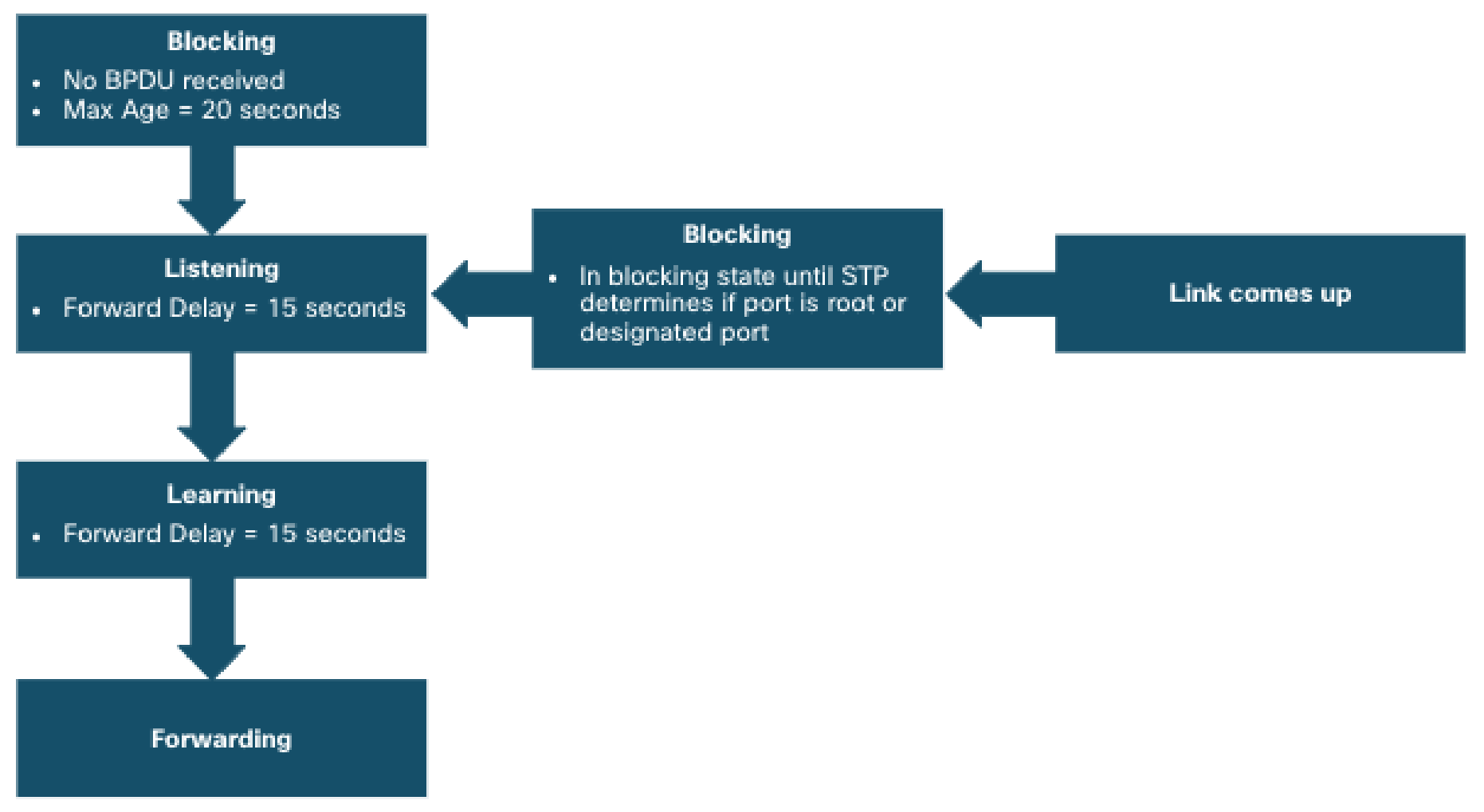
Every port on a switch using STP exist in one of the following five states:
| Port State | Description | Learns MACs based on Received Frames? | Forwards Data Frames? | Transitory or Stable State? |
|---|---|---|---|---|
| Disabled | The port is administratively disabled and does not participate in STP | No | No | Stable |
| Blocking | The port is enabled, listening for BPDUs but not forwarding any traffic | No | No | Stable |
| Listening | The port is sending and receiving BPDUs and determines the best path to the root bridge, also removing old stale (unused) MAC table entries | No | No | Transitory |
| Learning | The port is learning the MAC addresses of the devices connected to it and populating the MAC address table, but does not forward any traffic | Yes | No | Transitory |
| Forwarding | The port is forwarding traffic normally and participating in STP convergence | Yes | Yes | Stable |
STP Port Types Link to heading
| Port Type | Description |
|---|---|
| Point-to-point (P2P) | This port type connects with another network device (PC or RSTP switch). |
| P2P edge | This port type specifies that portfast is enabled on this port. |
STP Convergence Link to heading
- All root and designated ports are in a forwarding state and all other active ports are in a blocking state.
- The switches collectively realise that something has changed in the LAN topology and dynamically determine whether they need to change which ports block and which ports forward.
STP Timers Link to heading
| Timer | Default Value | Description |
|---|---|---|
| Hello | 2 seconds | Interval between Hello BPDUs sent by the root |
| MaxAge | 10 times Hello | How long any switch should wait, after ceasing to hear Hellos, before trying to change the STP topology |
| Forward Delay | 15 seconds | Time that is spent in the listening and learning state, which delays the process that occurs when an interface changes from blocking state to forwarding state |
STP Topology Changes Link to heading
BPDUs always flow from the root switch towards the edge switches, unless there are changes in the topology.
- The switch that detects a link status change sends a Topology Change Notification (TCN) BPDU out of its RP to the root switch.
- If an upstream switch receives the TCN, it sends out an acknowledgement and forwards the TCN out its RP to the root switch.
- Upon receipt of the TCN, the root switch creates a new configuration BPDU with the Topology Change flag set, and it is then flooded to all the switches.
- When switches receive this, they set their MAC address timer to a default 15 seconds. Then the device flushes its MAC table if has not heard from a device in that last 15 seconds.
- TCNs are generated on a VLAN basis, so the impact of TCNs directly correlates to the number of hosts in a VLAN.
Per-VLAN Spanning Tree Plus (PVST+) Link to heading
- A drawback to PVST+ is that there is solely one instance of PVST+ running for each VLAN in the network, regardless of whether there are different spanning-tree topologies required. This presents the potential for overwhelming the switch CPU and memory.
- Additionally, Cisco switches support a finite number of PVST instances. If more VLANs are created than there are PVST+ instances supported on a particular switch, some of the VLANs will not have any STP running, and therefore not having any switching loop protection.
- Rapid Per VLAN Spanning Tree (PVST+) is the Cisco implementation of RSTP on a
per-VLAN basis.
- Each VLAN runs an independent spanning tree instance of RSTP.
- The number of VLANs = the number of root switches existing in the topology
- To identify which VLAN is described by a BPDU:
- List the VLAN ID in the System ID Extension field of the BPDU
- Add the VLAN ID in an extra TLV field in the BPDU
- Add a VLAN tag when forwarding a BPDU over VLAN trunks
- The receiving switch can check all three locations that list the VLAN ID to ensure that they all agree about what VLAN the BPDU is describing.
Rapid Spanning Tree Protocol (RSTP) Link to heading
- Most parameters have been left unchanged, meaning anyone who has configured STP before can easily configure RSTP.
- RSTP increases recalculation speed and also reaches convergence faster.
- If a port is configured to be an alternate port, it can immediately change to a forwarding state without waiting for the network to converge.
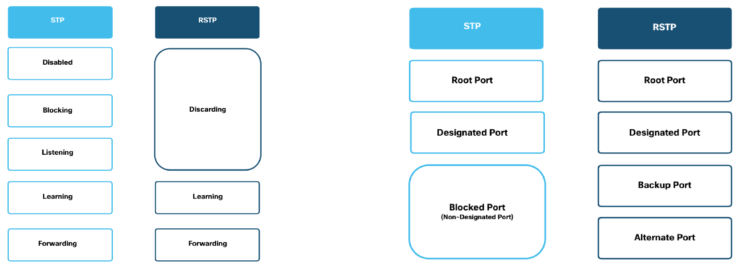
RSTP Port States Link to heading
- Discarding
- Learning
- Forwarding
RSTP Port Roles Link to heading
| Port Role | Description |
|---|---|
| Root Port (RP) | Port that begins a nonroot switch’s best path to the root |
| Alternate Port | Port that replaces the RP when the RP fails |
| Designated Port (DP) | Port that is designated to forward onto a collision domain |
| Backup Port | Port that replaces a DP when the DP fails |
| Disabled Port | Port that is administratively disabled |
- Alternate and Backup are two additional port types for blocked port:
- Backup ports apply only to designs that use hubs, so they are unlikely to be useful today.
STP versus RSTP Link to heading
Similarities Link to heading
- RSTP and STP elect the root switch using the same rules and tiebreakers.
- RSTP and STP switches select their root ports with the same rules.
- RSTP and STP elect designated ports on each LAN segment with the same rules and tiebreakers.
- RSTP and STP place each port in either forwarding or blocking state, although RSTP calls the blocking state the discarding state.
Differences Link to heading
- RSTP adds a mechanism by which a switch can replace its RP, without any waiting to reach a forwarding state (in some conditions).
- RSTP adds a new mechanism to replace a DP, without any waiting to reach a forwarding state (in some conditions).
- RSTP lowers waiting times for cases in which RSTP must wait for a timer.
Comparing Port States Link to heading
| Function | STP State | RSTP State |
|---|---|---|
| Port is administratively disabled | Disabled | Discarding |
| Stable state that ignores incoming data frames and is not used to forward data frames | Blocking | Discarding |
| Interim state without MAC learning and without forwarding | Listening | Not used |
| Interim state with MAC learning and without forwarding | Learning | Learning |
| Stable state that allows MAC learning and forwarding of data frames | Forwarding | Forwarding |
Multiple Spanning Tree (MST) Link to heading
Configuring and Verifying BID Link to heading
Regardless of the which per-VLAN Spanning Tree is used, two main configuration options can be used to achieve load-balancing:
- Bridge ID - The bridge ID influences the choice of root switch and can be configured per VLAN.
- Port cost - Each interface’s (per-VLAN) STP cost to reach the root influences the choice of designated port on each LAN segment.
Because PVST requires that a separate instance of spanning tree run for each VLAN, the BID field is required to carry VLAN ID (VID) information. This is accomplished by reusing a portion of the Priority field as the extended system ID to carry a VID.
STP defaults and configurations options:
| Setting | Default | Command(s) to Change Default |
|---|---|---|
| Bridge ID | Priority: 32,768 + VLAN ID System: A burned-in MAC on the switch | spanning-tree vlan vlan_# root <primary / secondary> spanning-tree vlan vlan_# priority priority_# |
| Interface cost | 100 for 10 Mbps, 19 for 100 Mbps, 4 for 1 Gbps, 2 for 10 Gbps | spanning-tree vlan vlan_# cost cost |
- The
primarykeyword sets the priority to 24576 or to the next 4096 increment value below the lowest bridge priority detected on the network. - The
secondarykeyword sets the priority to 28672, assuming the rest of the network is set to the default priority of 32768. - Alternatively, a specific priority value can be directly configured; however, priority value must be in increments of 4096 between 0 and 65536.
Cisco STP Toolkit Link to heading
Cisco recommends that you design for the use of the Cisco STP Toolkit to enhance the performance of IEEE 802.1D STP on your network.
| Mechanism | Improves STP Performance or Stability? | Description |
|---|---|---|
| PortFast | STP performance | Bypasses listening-learning phases to transition directly to the forwarding state |
| UplinkFast | STP performance | Enables fast uplink failover on an access switch |
| BackboneFast | STP performance | Enables fast convergence in distribution and core layers when STP changes occur |
| Loop Guard | STP stability | Prevents an alternate or root port from being the designated port in the absence of bridge protocol data units (BPDUs) |
| Root Guard | STP stability | Prevents external switches from becoming the root of the STP tree |
| BPDU Guard | STP stability | Disables a PortFast-enable port if a BPDU is received |
| BPDU Filter | STP stability | Suppresses BPDU on ports |
EtherChannel Link to heading
One of the best ways to lower STP’s convergence time is to avoid convergence altogether. EtherChannel provides a way to prevent STP convergence from being needed when only a single port or cable failure occurs.
PortFast Link to heading
Ports connected to non-switch, non-bridge, or non-hub devices should be configured with PortFast, such as PCs, servers, and routers. However, make sure that you PortFast is not enabled on a port connected to another L2 switch, since this might inadvertently be creating a L2 loop, which will create broadcast storms and the mislearning of MAC addressing information.
BPDU Guard Link to heading
- Security exposures may include:
- An attacker could connect a switch to one of these ports, one with a low STP/RSTP priority value, and become the root switch. The new STP/RSTP topology could have worse performance than the desired topology.
- The attacker could plug into multiple ports, into multiple switches, become root, and actually forward much of the traffic in the LAN. Without the networking staff realising it, the attacker could use a LAN analyser to copy large numbers of data frames sent through the LAN.
- Users could innocently harm the LAN when they buy and connect an inexpensive consumer LAN switch (one that does not use STP/RSTP). Such a switch, without any STP/RSTP function, would not choose to block any ports and could cause a loop.
- In addition, the BPDU Guard feature helps prevent problems with PortFast. PortFast should be enabled only on access ports that connect to user devices, not to other LAN switches. Using BPDU Guard on these same ports makes sense because if another switch connects to such a port, the local switch can disable the port before a loop is created.
Configuration Link to heading
Configure a specific access port (per interface):
| Task | IOS Command |
|---|---|
| Select an interface (port) to configure | Switch(config)# interface interface_# |
| Configure that port as an access port | Switch(config-if)# switchport mode access |
| Enable PortFast on the access port | Switch(config-if)# spanning-tree portfast |
| Verify the PortFast status | Switch# show spanning-tree interface interface_# portfast |
Configure all access ports (globally):
| Task | IOS Command |
|---|---|
| Enable PortFast globally on all access ports | Switch(config)# spanning-tree portfast default |
| Enable BPDU Guard globally on all access ports | Switch(config)# spanning-tree portfast bpduguard default |
| Enable PortFast on trunk ports | Switch(config)# spanning-tree portfast trunk |
Troubleshooting STP Link to heading
STP runs by default on switches and rarely causes problems in small- to medium-sized networks. However, if encountering STP problems, use the following steps to analyse:
- Determine the root switch.
- For each non-root switch, determine its one root port (RP) and cost to reach the root switch through that RP.
- For each segment, determine the designated port (DP) and the cost advertised by the DP onto that segment.
Troubleshooting commands:
| Task | IOS Command |
|---|---|
| Report on active interfaces only | Switch# show spanning-tree active |
| Provide a summary of connected spanning tree ports by VLAN | Switch# show spanning-tree summary |
| Show detailed information | Switch# show spanning-tree detail |
| Show the current state of the spanning tree for this VLAN ID | Switch# show spanning-tree vlan vlan_id(s) |
| Turn on debug for STP if having problems identifying what is causing the loop | Switch# debug spanning-tree events |