Table of Contents Link to heading
- Router
- Routing
- Routing Table
- Static Routing
- Static versus Dynamic Routing
- Administrative Distance (AD)
- Load Balancing
Router Link to heading
- It has a CPU, DRAM, and storage (ROM, NVRAM, Flash, Hard Drive/USB).
- It requires configuration on interfaces before it can be used.
- Each interface is on its own network (assigned unique IP addressing
information).
- Serial DCE ends must be given a clock rate.
- No two interfaces can be on the same network as the router will prevent this from happening.
- A router’s purpose include:
- Interconnecting networks, allowing you to visit other remote networks from your own local network.
- Forwarding packets not destined to themselves (unlike hosts).
- Determining the best path to send packets.
- Encapsulating according to the medium’s data link frame type, in the case
of a serial link: point-to-point, High Level Data Link Control (HDLC), or
other protocols.
- A switch does not perform these complex tasks.
- A router is often the default gateway for a network.
- All hosts on a network should have a default gateway.
- The host will consult with its default gateway when it requires to go to a separate network.
Routing Link to heading
- To forward a packet to a destination network, the router requires a route to that network.
- If a route to a destination network does not exist on the router, the packet will be forwarded to a default gateway.
- If no default gateway is configured, the packet will be discarded.
- The destination network can be a number of routers or hops away from the gateway.
- If the router has an entry for the network in its routing table, it would only indicate the next-hop router to which the packet is to be forwarded, not the exact route to the final router.
- The routing process uses a routing table to map the destination network address to the next hop and then forwards the packet to this next-hop address.
Routing Table Link to heading
- Lists IP address groupings, called IP networks and IP subnets.
- Consists of a list of prefixes (network address) and their associated prefix
length (subnet mask).
- e.g. 10.0.55.0/24.
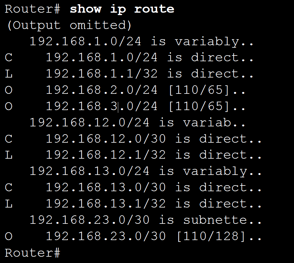
- Displayed using the command show ip route.
Learning Sources Link to heading
A routing table can be populated via three basic sources:
- Directly Connected Networks:
- When a router’s interface is configured with an IP address and subnet mask and is active (up), the interface becomes a host on that attached network.
- Remote Networks: only be reached by send the packet to another router.
- Using static routes: manually entered into the routing table, as long as the exit interface for the static route is active.
- Configuring dynamic routing protocols: learnt automatically by the router through sharing routes with other routers that use the same routing protocol.
- Default Route (Gateway of Last Resort - GWLR): if the destination address
does not match any entry in the routing table, the packet will be forwarded to
this default route if it is configured and active in the routing table.
- To be active, the configured next-hop address must be reachable.
- Read more at 🔗.
Principles Link to heading
There are three routing table principles according to Alex Zinin in his book, Cisco IP Routing.
| Principle | Example |
|---|---|
| Every router makes its decision alone, based on the information it has in its own routing table | R1 can only forward packets using its own routing table R1 does not know what routes are in the routing tables of other routers (e.g. R2) |
| The information in a routing table of one router does not necessarily match the routing table of another router | Just because R1 has route in its routing table to a network in the Internet via R2, that does not mean that R2 knows about that same network |
| Routing information about a path does not provide return routing information | R1 receives a packet with the destination IP address of PC1 and the source IP address of PC3. Just because R1 knows to forward the packet out its G0/0/0 interface, doesn’t necessarily mean that it knows how to forward packets originating from PC1 back to the remote network of PC3 |
Structure Link to heading
- A child route is an indented entry in the routing table. This occurs when
it is a subnet of a classful address.
- Child routes contain the route source and forwarding information.
- A parent route is above child routes and is slightly less indented, it will not have a route source code. The parent route will have the classful network address.
Entries Link to heading
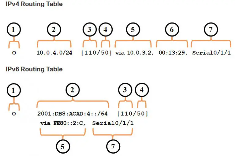
- Route source – how the route was learnt.
- Destination network – the address of the remote network and how that network is connected.
- Administrative distance – the trustworthiness of the route source.
- Metric – the value assigned to reach the remote network.
- Next hop – the IPv4 address of the next router to forward the packet to.
- Route timestamp – how much time elapsed since the route was learnt.
- Outgoing interface – the egress interface to use when forwarding packets to the destination network.
📓 Metric, next hop, and route timestamp values are only identified in routing table entries for routes to remote network.
Route Sources Link to heading
Sources for each route given in the routing table in the first column called a code which identifies how the route was learnt.
Common Codes include:
- L - Local route
- C - Directly connected network
- S - Static route configured manually to reach a specific network
- D - Dynamically learnt network from another router using the EIGRP routing protocol
- O - Dynamically learnt network from another router using the OSPF routing protocol
- R - Dynamically learnt network from another router using the RIP routing protocol
- Default route
Directly Connected Entries Link to heading
- A directly connected network is shown as a C routing status in the routing
table. This entry only gives the network prefix and prefix length.
- E.g. 192.168.1.0/24.
- There is also another entry for directly connected networks, which is the
local route - indicated by an L - which is the IP address of the local
interface and thus having a /32 prefix length.
- E.g. 192.168.1.1/32.
- The destination IP address must match all 32 bits in order to be directed to the local route.
- The purpose of the local route is to efficiently determine when it receives a packet for the interface instead of a packet it needs to be forwarded.
- You must configure at least one directly connected network (configure an interface with an IP address and activate it) for routing to learn about remote networks.
- Directly connected networks will always be child routes because the local address will always be /32.
Static Routing Link to heading
Path Determination Link to heading
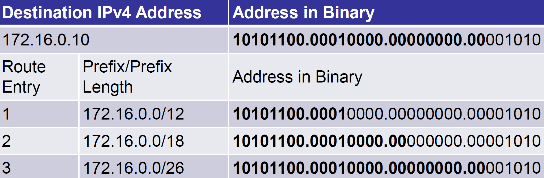
- To determine the best route, the router looks up its routing table for a network address that matches the packet’s destination IP address.
- The best route is the longest match.
- It means the best route is the one with the most consecutively matching far left bits in the prefix (network address) when compared to the IP address of the destination.
- One of three path determinations results from a routing table search:
- Directly connected network:
- If the destination IP address of the packet belongs to a device on a network that is directly connected to one of the router’s interfaces, that packet is forwarded directly to that device.
- This means that the destination IP address of the packet is a host address on the same network as this router’s interface.
- Remote network:
- If the destination IP address of the packet belongs to a remote network, the packet is forwarded to a another router (specifically next-hop router).
- Remote networks can be reached only by forwarding packets to another router.
- No route determined:
- If the destination IP address of the packet does not belong to either a connected or remote network, and the router does not have a default route, the packet is discarded.
- The router sends an Internet Control Message Protocol (ICMP) Unreachable message to the source IP address of the packet.
- Directly connected network:
Take the routing entries below, we compare the address in binary and determine the best path or where best to send it. In this case, 172.16.0.0/26 is the longest, thus it gets sent to the interface associated with 172.16.0.0/26.
Packet Forwarding Mechanisms Link to heading
Much like a switch, there are different ways routers packet forward:
- Process switching - solves a problem by doing maths long hand, even if it
is the identical problem.
- Slowest, all traffic goes to the control plane to be processed by the CPU, no caching.
- Fast switching - solves a problem by doing maths long hand one time and
remembering the answer for subsequent identical problems.
- Slow, Process Switching but with a cache to prevent overuse of the CPU.
- Cisco Express Forwarding (CEF) switching - solves every possible problem
ahead of time in a spreadsheet.
- Most recent and default for IOS packet forwarding. CEF builds a Forwarding Information Base (FIB) and an adjacency table.
- Table entries are not packet-triggered like fast switching but are instead change-triggered. When a change happens in the topology, the tables are updated.
- The FIB and adjacency tables are created during network convergence and contain all information required to forward packets.
The packet forwarding decision process can be described as follows:
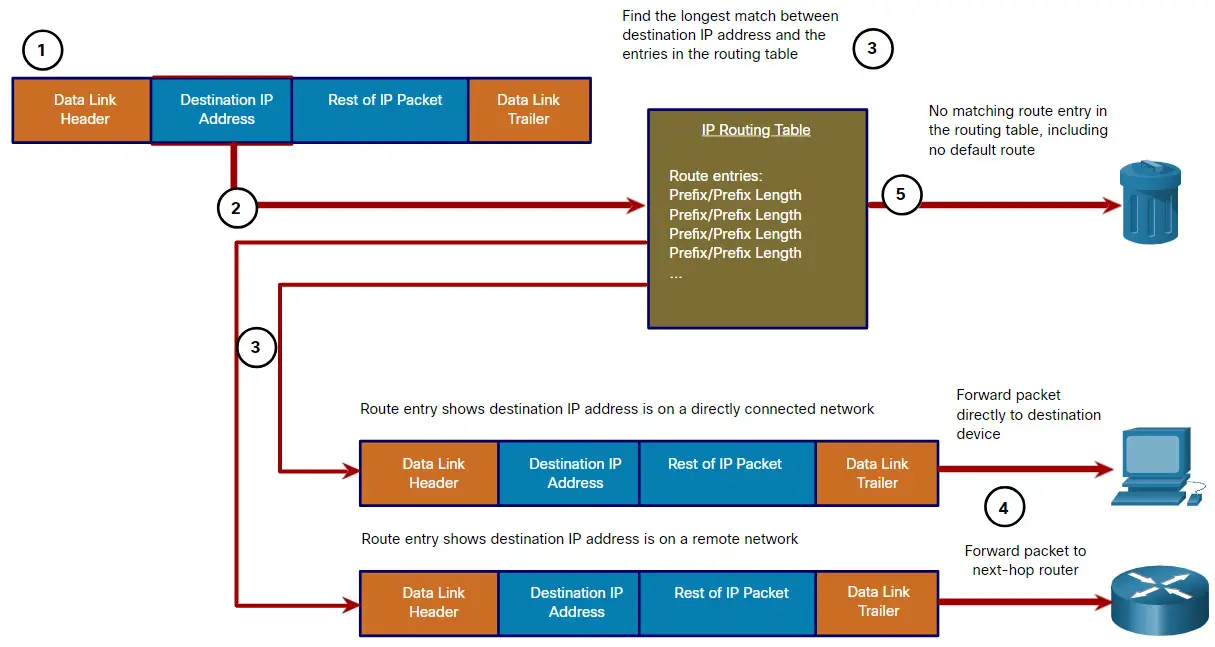
- The data link frame with encapsulated IP packet arrives on the ingress interface.
- Router examines destination IP address in packet header, consults IP routing table.
- Router finds the longest matching prefix in the routing table.
- Router encapsulates the packet in a data link frame and forwards it out the egress interface. Destination could be a connected device or a next-hop router.
- However, if there is no matching route entry, the packet is discarded.
Static versus Dynamic Routing Link to heading
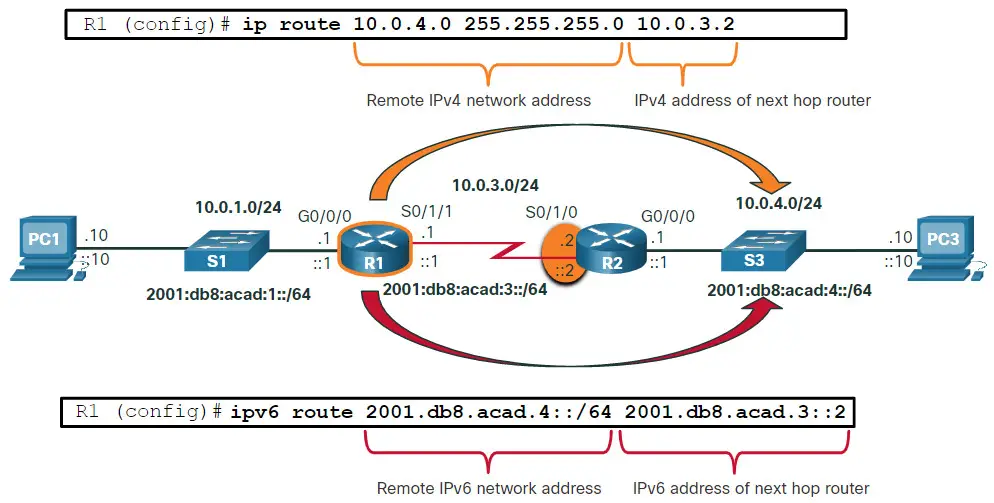
After directly connected interfaces are configured and added to the routing table, static and/or dynamic routing can be implemented for accessing remote networks since they are not mutually exclusive.
However, in terms of trustworthiness, static routes are prioritised owing to the AD of 1.
Static Routing Link to heading
- Advantages:
- Static routes are not advertised over the network, resulting in better security.
- Static routes use less bandwidth than dynamic routing protocols, as routers do not exchange routes.
- No CPU cycles are used to calculate and communicate routes.
- The path a static route uses to send data is known.
- Disadvantages:
- Initial configuration and maintenance is time-consuming.
- Configuration can be error-prone, especially in large networks.
- Administrator intervention is required to maintain changing route information.
- Does not scale well with growing networks; maintenance becomes cumbersome.
- Requires complete knowledge of the whole network for proper implementation.
Static routes are commonly used when:
A default route is required to direct traffic to a specific destination device.
- e.g. a default route forwarding packets to a service provider.
Routes are outside the routing domain and not learnt by the dynamic routing protocol.
The network is small enough and is not expected to grow significantly.
The network administrator wants to explicitly define the path for a specific network.
Routing information is not exchanged.
- e.g. at network boundaries, such as Internet or partners.
No routing protocols are configured.
- e.g. static routes defined in remote WAN routers in a hub-and-spoke WAN.
Routing between stub networks - there is only one path to an outside network (the router has only one neighbour).
- e.g. a home router to its ISP.
They are also useful when:
- Summarising routes to reduce the number of routes advertised.
- Creating a backup route to take over in case a primary route link fails.
- Providing security in a larger network for certain types of traffic, or links to other networks that need more control.
- Static routes are viable when there are few routes to enter. As networks grow larger, they need to implement dynamic routing.
Dynamic Routing Link to heading
Only one dynamic routing protocol should be active on a router, unless exceptional circumstances demand for more than one.
Dynamic routing protocols perform several activities, including:
- Discovery of remote networks - the ability to share information about the networks it knows about with other routers that are using the same routing protocol.
- Maintenance of routing tables - the ability to compensate for any topology change without involving the network administrator (e.g. find a new best route if the current path is not available).
There are many different protocols, some popular choices include:
- RIP - Routing Information Protocol, often used to educate
- IGRP - Interior Gateway Routing Protocol
- EIGRP - Enhanced Interior Gateway Routing Protocol
- OSPF - Open Shortest Path First
- IS-IS - Intermediate System-to-Intermediate System
- BGP - Border Gateway Protocol
Advantages:
- Suitable in all topologies where multiple routers are required.
- Generally independent of the network size.
- Automatically adapts topology to reroute traffic if possible.
Disadvantages:
- Can be more complex to initially implement.
- Less secure due to the broadcast and multicast routing updates. Additional configuration settings such as passive interfaces and routing protocol authentication are required to increase security.
- Route depends on the current topology.
- Requires additional resources, such as CPU, memory, and link bandwidth.
Dynamic routing protocols are commonly used when:
- In networks consisting of more than just a few routers.
- A change in the network topology requires the network to automatically determine another path.
- The network is likely to grow, the dynamic routing protocol automatically learns about any new networks and determines better routes, hence scalability.
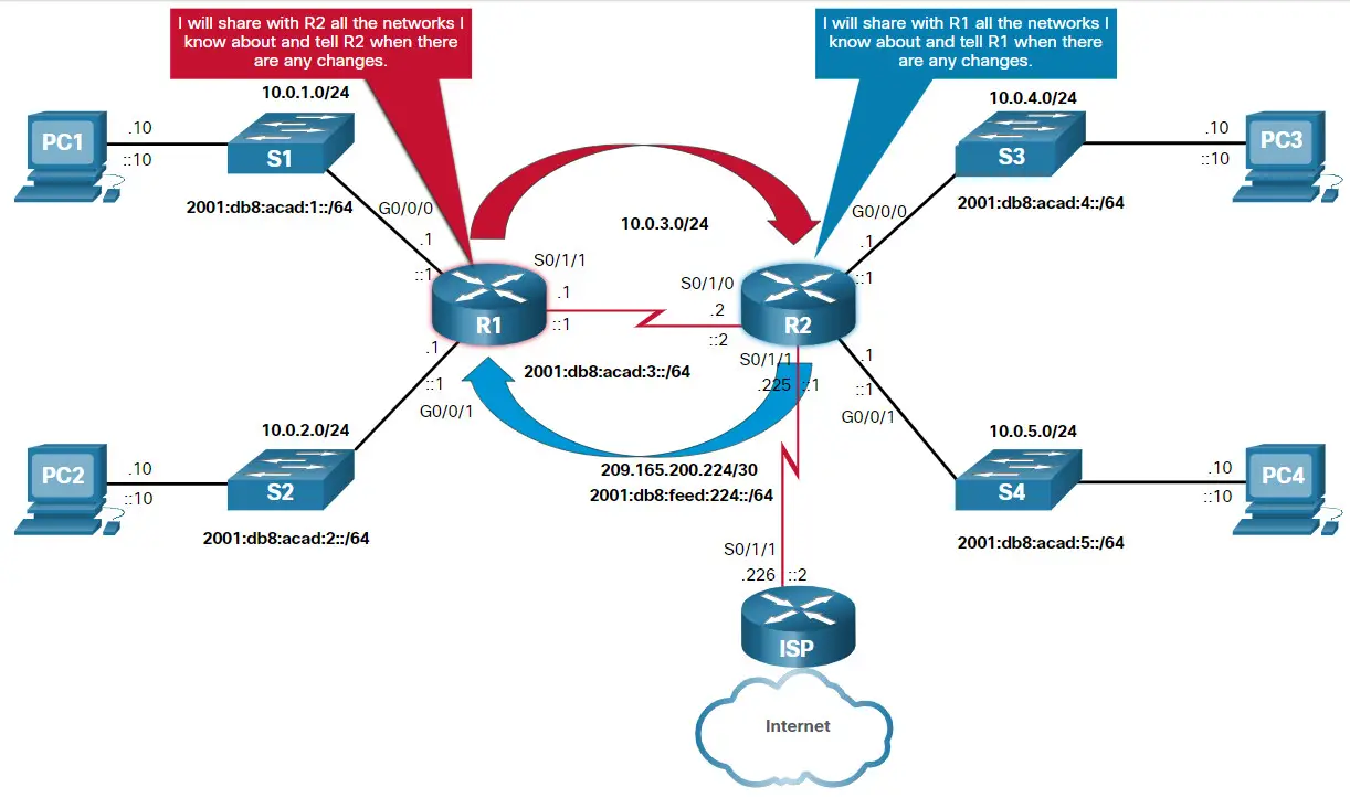
The figure below shows routers R1 and R2 using a common routing protocol to share network information.
Summary Link to heading
| Feature | Dynamic Routing | Static Routing |
|---|---|---|
| Configuration complexity | Independent of network size | Increases with network size |
| Topology changes | Automatically adapts to topology changes | Administrator intervention required |
| Scalability | Suitable for simple to complex network topologies | Suitable for simple topologies |
| Security | Security must be configured | Security is inherent |
| Resource Usage | Uses CPU, memory, and link bandwidth | No additional resources needed |
| Path Predictability | Route depends on topology and routing protocol used | Explicitly defined by the administrator |
Administrative Distance (AD) Link to heading
Static Routing Usage Link to heading
Dynamic Routing Usage Link to heading
- Since there can only be a route entry for a specific network address in the routing table.
- Therefore, if multiple routing protocols have different routes leading to the
same destination, only one can be installed into the routing table.
- The lower the AD, the more trustworthy the route source.
- The best route has the lowest AD.
- If a router receives a route to a certain network from both an OSPF routing
process (default AD - 110) and a RIP routing process (default AD - 120), the
OSPF route will be chosen because OSPF is more trustworthy.
- In this case, the router adds the OSPF version of the route to the routing table.
- If the source of the OSPF-derived route was lost (for example, due to a power shutdown), then the RIP-derived route will be used until the OSPF-derived route reappears.
| Route Source | Administrative Distance |
|---|---|
| Directly connected | 0 |
| Static route | 1 |
| EIGRP summary | 5 |
| External BGP | 20 |
| Internal EIGRP | 90 |
| IGRP | 100 |
| OSPF | 110 |
| IS-IS | 115 |
| RIPv1/2 | 120 |
| EGP | 140 |
| External EIGRP | 170 |
| Internal BGP | 200 |
| Unknown | 255 |
Load Balancing Link to heading
- In case a router has more than one path to a destination with identical cost metrics, it will load balance traffic across all paths.
- This is called equal-cost load balancing.
- The routing table contains the single destination network, but has multiple exit interfaces, one for each equal cost path.
- The router forwards packets using the multiple exit interfaces listed in the routing table.
- This improves network performance by reducing the overload on a single link, thereby increasing the effectiveness and performance of the network.
- Equal cost load balancing is implemented automatically by dynamic routing protocols and on static routes when there are multiple paths to the same network with different next-hop routers.
- By default, Cisco routers can load balance up to four equal cost paths.
- RIP and OSPF support equal cost load balancing.
- EIGRP is the only protocol to support both equal and unequal-cost load
balancing - when a router distributes traffic over network interfaces,
despite their different distances from the destination address.
- This feature gives EIGRP a significant advantage over other routing protocols.