
Table of Contents Link to heading
- OSI Data Link Layer
- Perspectives of Other Layers
- Data Link Sublayers
- Logical Link Control (LLC) Sublayer
- Media Access Control (MAC) Sublayer
- How L3 Routing Uses LANs
- IEEE 802 Standards
OSI Data Link Layer Link to heading
For packets to be transported from source host to destination host, they must traverse different physical networks (e.g., copper wires, microwaves, optical fibers, and satellite links), but network layer packets do not have a way to directly access these different media.
- Allow the upper layers to access the media using techniques such as framing
- Control how data is placed onto the media and is received from the media using techniques such as MAC and error detection
In any given exchange of network layer packets, there can be numerous data link layer and media transitions. At each hop along the path, an intermediary device, usually a router, processes the frame as follows:
- Accept the frame from a medium
- Decapsulate the frame into a packet
- Construct a new frame appropriate for the next media
- Forward the packet inside the new frame across the next segment of the physical network
At each hop, the received frame is also examined for errors. If an error is found in a received frame, the frame is discarded. If the frame is good, the data link layer directs the packet to an upper-layer protocol, in this case IPv4 or IPv6.
Perspectives of Other Layers Link to heading
The data link layer prepares communication for the media. The functions of the upper layers of the node are not aware what media the communication will use or over how many different media the communication can travel.
Data Link Sublayers Link to heading
To support a wide variety of network functions, the data link layer is divided into two sublayers:
- Logical Link Control (LLC): upper sublayer
- Media Access Control (MAC): lower sublayer
Logical Link Control (LLC) Sublayer Link to heading
Ethernet Network Interface Cards (NICs) Link to heading
In a computer, the LLC can be considered the driver software for the NIC.
The NIC driver is a program that interacts directly with the hardware on the NIC to enable the NIC to perform intermediary functions of preparing data for transmission and encoding the data as signals to be sent on the associated media.
Media Access Control (MAC) Sublayer Link to heading
Encapsulating Packets into Frames Link to heading
When packets have been encapsulated at the data link layer, they are referred to as frames.
Each L2 protocol uniquely describes what control information is required and how that information is included in the encapsulation.
Framing Link to heading
Three basic elements of a frame:
- Data - the packet from the network layer
- Header - the control information, such as source/destination MAC addressing and frame type/length, located at the beginning of the PDU
- Trailer - the control information, such as a checksum/CRC, added to the end of the PDU
Minimum Frame Size Link to heading
Any frame less than 64 bytes in length is considered a collision fragment or runt frame, while any frame more than 1500 in length is considered a jumbo frame or baby giant frame.
If the frame size is less than 64 bytes, the receiving device automatically drops the frame.
Jumbo frames are supported by most Fast Ethernet and Gigabit Ethernet switches and NICs. However, if a receiving device does not support jumbo frames, it may discard the frame as invalid or oversized, or attempt to fragment it into smaller frames, which can result in data loss, errors, or reduced performance.
Role of Header Link to heading
| Header Field Name | Description |
|---|---|
| Start of Frame | Indicates the beginning of the frame |
| Source and Destination address | Indicate the source and destination nodes on the media |
| Priority/Quality of Service | Indicates a particular type of communication service for processing |
| Type | Indicates the upper-layer service contained in the frame |
| Logical connection control | Used to establish a logical connection between nodes |
| Physical link control | Used to establish the media link |
| Flow control | Used to start and stop traffic over the media |
| Congestion control | Indicates congestion in the media |
Different L2 protocols can use different field names from those mentioned.
Role of Trailer Link to heading
| Trailer Field Name | Description |
|---|---|
| Frame Check Sequence (FCS) | Used for error checking of the frame contents |
| End of Frame | Used to indicate the end of the frame Also, can be used to increase the size of a frame to an expected fixed size or minimum size. |
Error Detection Link to heading
Error detection is added at L2 because this is where data is transferred across the media which is a potentially unsafe environment for data. The signals on the media is susceptible to interference, distortion, or loss that would change the bit values that those signals represent.
When the frame arrives at the destination node, the receiving node calculates its own CRC of the frame. The receiving node compares the two CRC values. If the two values are the same, the frame is considered to have arrived as it was transmitted. If the CRC value in the FCS differs from the CRC calculated at the receiving node, the frame is discarded.
Some L2 protocols, such as HDLC or PPP, also use acknowledgement and retransmission to ensure reliable delivery of frames.
Data-Link Protocols Link to heading
Which L2 protocol is used depends on the logical topology of the network and the implementation of the physical layer.
Given the wide range of physical media used across the range of topologies in networking, there are a correspondingly high number of L2 protocols in use.
A number of different network devices can act as nodes that operate at L2 when implementing these protocols, including NICs on computers as well as the interfaces on routers and L2 switches.
Ethernet Protocol for LANs Link to heading
Ethernet standards define both the L2 protocols and the L1 technologies.
Ethernet is the most widely used LAN technology and supports data bandwidths of 10, 100, 1000, or 10,000 Mbps.
There are two styles of Ethernet framing: IEEE 802.3 (original) and the revised IEEE 802.3 (the addition of a Start Frame Delimiter (SFD) field and a small change to the Type field to include the Length).
- The original Ethernet standard defined the minimum frame size as 64 bytes and the maximum as 1518 bytes. This includes all bytes from the Destination MAC Address field through the Frame Check Sequence (FCS) field. The Preamble and Start Frame Delimiter fields are not included when describing the size of a frame.
- The IEEE 802.3ac standard extended the maximum allowable frame size to 1522 bytes. The frame size increased to accommodate a technology used in switched networks called virtual local-area network (VLAN)
Preamble (7 bytes) and Start Frame Delimiter (SFD) (1 byte) Link to heading
These first 8 bytes of the frame get the attention of the receiving nodes. Essentially, the first few bytes tell the receivers to get ready to receive a new frame.
Destination MAC Address (6 bytes) Link to heading
This L2 address assists devices in determining whether a frame is intended for them. The device compares its MAC address to this address in the frame. If there is a match, the device accepts the frame.
Switches also use this address to determine out which interface to forward the frame.
Source MAC Address (6 bytes) Link to heading
Switches also use this address to add to entries in their lookup tables.
Length/Type (2 bytes) Link to heading
This is used later as part of the CRC process to ensure that the message was received properly. This can be either a length or a type value. However, only one or the other can be used in a given implementation.
Once receiving a frame, the receiving node must examine the Length/Type field to determine which upper-layer protocol is present. If the two-octet value is equal to or greater than 0x0600 hexadecimal or 1536 decimal, the contents of the Data field are decoded according to the protocol indicated.
Data and Pad (46–1500 bytes) Link to heading
All frames must be at least 64 bytes long. If the encapsulated packet is small, the Pad increases the size of the frame to this minimum size.
Frame Check Sequence (FCS) (4 bytes) Link to heading
It uses a CRC. The sending device includes the results of a CRC in the FCS field of the frame. The receiving device receives the frame and generates a CRC from the frame contents. If the calculations match, no error has occurred. Calculations that do not match are an indication that the data has changed. Therefore, the frame is dropped. A change in the data could be the result of a disruption of the electrical signals that represent the bits.
Point-to-Point Protocol (PPP) for WANs Link to heading
PPP can be used on various physical media, including twisted-pair cable, fibre-optic lines, and satellite transmission, as well as for virtual connections.
PP uses a layered architecture. To accommodate the different types of media, PPP establishes logical connections, called sessions, between two nodes. The PPP session hides the underlying physical media from the upper-layer protocol. These sessions also provide PPP with a method for encapsulating multiple upper-layer protocols over a point-to-point link. Each protocol encapsulated over the link establishes its own PPP session.
A PPP frame contains the following fields:
- Flag: A single byte that indicates the beginning or end of a frame. The flag field consists of the binary sequence 01111110.
- Address: A single byte that contains the standard PPP broadcast address. PPP does not assign individual station addresses.
- Control: A single byte that contains the binary sequence 00000011, which calls for transmission of user data in an unsequenced frame.
- Protocol: Two bytes that identify the protocol encapsulated in the data field of the frame. The most up-to-date values of the protocol field are specified in the most recent Assigned Numbers RFC.
- Data: Zero or more bytes that contain the datagram for the protocol specified in the protocol field.
- FCS: Normally 16 bits (2 bytes). By prior agreement, consenting PPP implementations can use a 32-bit (4-byte) FCS for improved error detection.
Wireless Protocol (Wi-Fi) for LANs Link to heading
A 802.11 frame contains the following fields:
- Protocol Version: Version of 802.11 frame in use
- Type and Subtype: Identifies one of three functions and subfunctions of the frame: control, data, and management
- To DS: Set to 1 in data frames destined for the distribution system (devices in the wireless structure)
- From DS: Set to 1 in data frames exiting the distribution system
- More Fragments: Set to 1 for frames that have another fragment
- Retry: Set to 1 if the frame is a retransmission of an earlier frame
- Power Management: Set to 1 to indicate that a node will be in power-save mode
- More Data: Set to 1 to indicate to a node in power-save mode that more frames are buffered for that node
- Wired Equivalent Privacy (WEP): Set to 1 if the frame contains WEP-encrypted information for security
- Order: Set to 1 in a data type frame that uses Strictly Ordered service class (does not need reordering)
- Duration/ID: Depending on the type of frame, represents either the time, in microseconds, required to transmit the frame or an association identity (AID) for the station that transmitted the frame
- Destination Address (DA): MAC address of the final destination node in the network
- Source Address (SA): MAC address of the node that initiated the frame
- Receiver Address (RA): MAC address that identifies the wireless device that is the immediate recipient of the frame
- Transmitter Address (TA): MAC address that identifies the wireless device that transmitted the frame
- Sequence Number: Indicates the sequence number assigned to the frame; retransmitted frames are identified by duplicate sequence numbers
- Fragment Number: Indicates the number for each fragment of a frame
- Frame Body: Contains the information being transported; for data frames, typically an IP packet
- FCS: Contains a 32-bit cyclic redundancy check (CRC) of the frame
Other Protocols Link to heading
High-level Data Link Control (HDLC) is used in point-to-multipoint connections and most commonly used in point-to-point serial communications.
Frame Relay is used in nonbroadcast multiaccess (NBMA) networks, such as WAN-connected sites.
ATM is the international standard for cell relay in which devices send multiple service types, such as voice, video, or data, in fixed-length.
Placing Frames onto the Media Link to heading
IEEE 802.3 MAC sublayer includes the specifications for different Ethernet communications standards over various types of media.
Transferring Frames across Local Media Link to heading
At intermediary devices, such as routers, where the media type could change for each connected network, different physical interfaces encapsulate the packet into the appropriate frame and a suitable MAC method is used to access each link.
For example, a router has an Ethernet interface to connect to the LAN and a serial interface to connect to the WAN, the router processes the frame as follows:
- Use an Ethernet-supported data link layer protocol to receive the frame from one medium.
- Decapsulate the frame into a packet.
- Re-encapsulate the packet into a new frame supported by the protocol used in the WAN.
- Place the new frame onto the medium of the next link of the network.
MAC Method Link to heading
The MAC method used depends on:
- Media sharing: If and how the nodes share the media
- Topology: How the connection between the nodes appears to the data link layer
Media Sharing Link to heading
MAC for Shared Media (Multiaccess Networks) Link to heading
Some examples of multiaccess networks are Ethernet, WiFi, Frame Relay, and ATM.
A multiaccess network requires a MAC method to coordinate the access and avoid collisions or interference among the devices.
The two basic MAC methods for shared media are as follows:
- Controlled: Each node has its own time to use the medium.
- Contention-based: All nodes compete for the use of the medium.
Controlled Access (Deterministic Method) Link to heading
Examples: Token Ring and Fibre Distributed Data Interface (FDDI) networks.
A controlled access method provides predictable throughput and prevents collisions, but it can be inefficient because a device has to wait for its turn before it can use the medium.
Contention-Based Access (Nondeterministic Method) Link to heading
Examples: legacy Ethernet and WLANs.
However, it is possible that the CSMA process will fail and two devices will transmit at the same time, resulting in a collision where the data sent by both devices will be corrupted and will need to be resent.
Unlike controlled access methods, a mechanism for tracking whose turn it is to access the media is not required, hence less overhead.
However, the contention-based systems do not scale well under heavy media use. The higher the use and the number of nodes, the higher the probability of a collision occurs, resulting in diminished throughput.
CSMA is usually implemented in conjunction with a mechanism for resolving the media contention.
If a data signal is absent, indicating that the media is free, the device transmits the data. If signals are then detected that show another device was transmitting at the same time, all devices stop sending and try again later.
This method is used in Ethernet networks.
There are three steps in the CSMA/CD process:
- Listen before sending
- A device with a frame to send must listen before transmitting the frame. If a device detects a signal from another device, it will wait for a specified amount of time before attempting to transmit.
- If the device does not detect any signal, it will transmit its frame.
- Detect a collision
- If a device does not detect the signal from a second device, the first device can also start to transmit. The media now has two devices transmitting their signals at the same time, creating a collision on the shared media.
- Their messages will propagate across the media until they encounter each other. At that point, the signals mix, a collision occurs, and the message is destroyed.
- Although the messages are corrupted, the jumble of remaining signals continues to propagate across the media. While this transmission is occurring, the device continues to listen to the media to determine whether a collision occurs.
- If the frame is sent without a collision being detected, the device returns to its listening mode.
- Jam signal and random backoff
- When a collision occurs, the transmitting devices that detect the
collision will continue to transmit a 32-bit jam signal for a specific
period to notify all devices on the network of a collision.
- Being 32-bit in length ensures that a jam signal is not detected as a valid frame; otherwise, the collision would not be identified.
- The device receiving the jam signal will invoke a random backoff timer that stop itself from transmitting for a random amount of time, which allows the collision signals to subside and the media to stabilise.
- After the frame has been sent without collision or the backoff delay has expired on a device, the device goes back into the “listen before sending” mode.
- When a collision occurs, the transmitting devices that detect the
collision will continue to transmit a 32-bit jam signal for a specific
period to notify all devices on the network of a collision.
If the media is free, the device sends a notification across the media of its intent to use it. The device then sends the data.
This method is used in wireless networks.
MAC for Nonshared Media (Point-to-Point Networks) Link to heading
Since the nodes do not share the media with anyone or determine whether a frame is destined for that node, there is little or no control before placing frames onto the media.
In point-to-point connections, the data link layer has to consider whether the communication is half duplex or full duplex.
Half-Duplex Communication Link to heading
Legacy Ethernet uses hubs operated in a physical star topology and a logical bus topology over a shared, half-duplex medium. Half-duplex communication requires access control through CSMA/CD to detect collisions and thus ensure that only one device is transmitting at a time.
- Timing and Synchronisation
- If a collision has not occurred, the sending device will transmit 64 bits of timing synchronisation information, which is known as the Preamble. The sending device will then transmit the complete frame.
- Slot Time
- Slot time for a network is the maximum time required to detect a collision. This is equal to twice the time it takes a signal to travel between the two most-distant stations on the network.
- This ensures that all devices start to receive a frame before the transmitting NIC has finished sending it.
- Slot time is used to establish the following:
- The minimum size of an Ethernet frame
- A limit on the maximum size of a network’s segment
Full-Duplex Communication Link to heading
Duplex Mismatch Link to heading
Current Ethernet uses switches operated in a physical star topology and a logical point-to-point topology over a full-duplex medium. Full-duplex communication with Ethernet switches does not require access control through CSMA/CD.
Topology Link to heading
Bus Topology Link to heading
In a bus topology, where all devices are connected to a single cable, the MAC method needs to prevent collisions and handle contention among the devices.
A common MAC method for bus networks is CSMA/CD, which allows devices to sense the medium before transmitting and to stop and retry if a collision occurs.
Ring Topology Link to heading
In a ring topology, where all devices are connected in a loop, the MAC method needs to ensure that each device gets a fair chance to transmit and to avoid deadlock.
A common MAC method for ring networks is token passing, which involves passing a special message called a token around the ring. Only the device that has the token can transmit, and it must release the token after a certain time.
Star Topology Link to heading
In a star topology, where all devices are connected to a central device, such as a hub or a switch, the MAC method needs to manage the traffic and congestion at the central device.
A common MAC method for star networks is polling, which involves the central device asking each device in turn if it has data to send. This method avoids collisions and ensures that each device gets a turn, but it can be inefficient and slow.
Mesh Topology Link to heading
In a mesh topology, where each device is connected to every other device, the MAC method needs to coordinate the transmissions and avoid interference among the devices.
A common MAC method for mesh networks is TDMA (time division multiple access). This method divides the medium into time slots and assigns each device a slot to transmit. This method avoids collisions and ensures high bandwidth, but it requires synchronisation and scheduling.
Point-to-Point and Hub-and-Spoke Topology Link to heading
For point-to-point and hub-and-spoke topologies, the MAC method is usually simpler and more efficient than for other topologies. This is because point-to-point and hub-and-spoke topologies have less contention and collision issues, as each device has a dedicated link to another device or to a central hub. Therefore, the MAC method does not need to implement complex mechanisms to avoid or resolve collisions. Instead, the MAC method can use simpler methods, such as polling or TDMA, to coordinate the access and transmission of data.
How L3 Routing Uses LANs Link to heading
The major steps in a router’s internal L3 routing for each packet beginning with a frame arriving in a router interface are:
- Use the data-link FCS field to ensure that the frame had no errors; if errors occurred, discard the frame.
- Assuming that the frame was not discarded at Step 1, discard the old data-link header and trailer, leaving the IP packet.
- Compare the IP packet’s destination IP address to the routing table, and find the route that best matches the destination address. This route identifies the outgoing interface of the router and possibly the next-hop router IP address.
- Encapsulate the IP packet inside a new data-link header and trailer, appropriate for the outgoing interface, and forward the frame.
Consider the following scenario where PC1 needs to communicate with PC2:
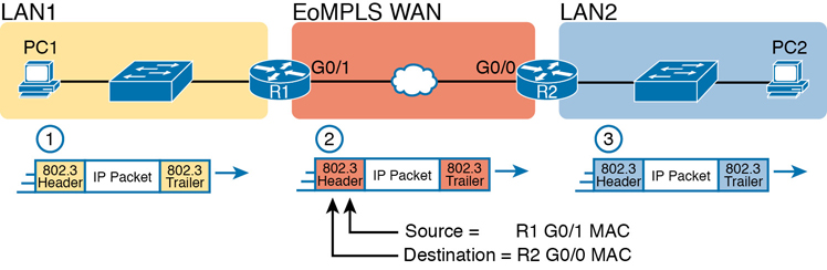
PC1 analyses the destination address and realises that PC2’s address is not on the same LAN as PC1. So PC1’s logic tells it to send the packet to a device whose job it is to know where to route data: a nearby router, on the same LAN, called PC1’s default router.
- To send the IP packet to R1, PC1 encapsulates the IP packet in an Ethernet frame with the destination MAC address of R1.
- R1 decapsulates the IP packet from the Ethernet frame and encapsulates the packet into a new Ethernet frame, with a new Ethernet header and trailer. The new destination MAC address is R2’s G0/0 MAC address, and the source MAC address is R1’s G0/1 MAC address.
- R2 decapsulates the IP packet from the Ethernet frame, encapsulates the packet into an Ethernet frame with the destination MAC address of PC2, and forwards the Ethernet frame to PC2.
Address Resolution Protocol (ARP) Link to heading
Because of the need to build new data-link headers and trailers, and because the new headers contain new data-link addresses, the PCs and routers must have some way to decide what data-link addresses to use. This introduces the need for the IP Address Resolution Protocol (ARP).
IEEE 802 Standards Link to heading
| IEEE 802 Standard | Topic |
|---|---|
| 802.1 | LAN/MAN/WAN management; protocol layers above the MAC and LLC sublayers |
| 802.2 | LLC sublayer |
| 802.3 | MAC sublayer and Physical layer |
| 802.3ac | Virtual LAN (VLAN) |
| 802.4 | Token Passing Bus |
| 802.5 | Token Passing Ring |
| 802.6 | Distributed Queue Dual Bus (DQDB) Metropolitan Area Network (MAN) |
| 802.7 | Broadband Local Area Networks |
| 802.8 | Fibre-Optic LANs and MANs |
| 802.9 | Isochronous LANs |
| 802.10 | LAN/MAN Security |
| 802.11 | Wireless LAN (WLAN) |
| 802.12 | Demand Priority Access Method |
| 802.15 | Wireless PAN (WPAN) |
| 802.16 | Wireless Metropolitan Area Network (WiMAX) |
| 802.17 | Resilient Packet Ring |
| 802.18 | LAN/MAN Standards Committee |