Table of Contents Link to heading
- Subnet or Subnetwork
- Subnetting
- Subnet Mask
- Subnetting Tips
- Classful Subnetting
- Classless Subnetting
- Variable-Length Subnet Masks (VLSMs)
- Supernet or Supernetwork
- Supernetting
- Subnetting versus Supernetting
- IP Addressing Design Considerations
Subnet or Subnetwork Link to heading
Subnetting Link to heading
- Complete IP address exhaustion has been prevented.
- Network traffic can travel a shorter distance without passing through unnecessary routers to reach its destination.
Subnet Mask Link to heading
- 255.255.255.0 in bits is equal to 11111111.11111111.11111111.00000000
- The zeros are host bits, the ones are network bits.
CIDR Prefix or Prefix Length Link to heading
| Subnet Mask | CIDR Prefix |
|---|---|
| 0.0.0.0 | /0 |
| 128.0.0.0 | /1 |
| 192.0.0.0 | /2 |
| 224.0.0.0 | /3 |
| 240.0.0.0 | /4 |
| 248.0.0.0 | /5 |
| 252.0.0.0 | /6 |
| 254.0.0.0 | /7 |
| 255.0.0.0 | /8 |
| 255.128.0.0 | /9 |
| 255.192.0.0 | /10 |
| 255.224.0.0 | /11 |
| 255.240.0.0 | /12 |
| 255.248.0.0 | /13 |
| 255.252.0.0 | /14 |
| 255.254.0.0 | /15 |
| 255.255.0.0 | /16 |
| 255.255.128.0 | /17 |
| 255.255.192.0 | /18 |
| 255.255.224.0 | /19 |
| 255.255.240.0 | /20 |
| 255.255.248.0 | /21 |
| 255.255.252.0 | /22 |
| 255.255.254.0 | /23 |
| 255.255.255.0 | /24 |
| 255.255.255.128 | /25 |
| 255.255.255.192 | /26 |
| 255.255.255.224 | /27 |
| 255.255.255.240 | /28 |
| 255.255.255.248 | /29 |
| 255.255.255.252 | /30 |
| 255.255.255.254 | /31 |
| 255.255.255.255 | /32 |
Borrowing Host Bits Link to heading
| CIDR Prefix | # IP Addresses = 2n | # Usable IP Addresses = 2n-2 |
|---|---|---|
| /32 | 1 | 1 |
| /31 | 2 | 2* |
| /30 | 4 | 2 |
| /29 | 8 | 6 |
| /28 | 16 | 14 |
| /27 | 32 | 30 |
| /26 | 64 | 62 |
| /25 | 128 | 126 |
| /24 | 256 | 254 |
| /23 | 512 | 510 |
| /22 | 1024 | 1022 |
| /21 | 2048 | 2046 |
| /20 | 4096 | 4094 |
| /19 | 8192 | 8190 |
| /18 | 16,384 | 16,382 |
| /17 | 32,768 | 32,766 |
| /16 | 65,536 | 65,534 |
| /15 | 131,072 | 131,070 |
| /14 | 262,144 | 262,142 |
| /13 | 524,288 | 524,286 |
| /12 | 1,048,576 | 1,048,574 |
| /11 | 2,097,152 | 2,097,150 |
| /10 | 4,194,304 | 4,194,302 |
| /9 | 8,388,608 | 8,388,606 |
| /8 | 16,777,216 | 16,777,214 |
| /7 | 33,554,432 | 33,554,430 |
| /6 | 67,108,864 | 67,108,862 |
| /5 | 134,217,728 | 134,217,726 |
| /4 | 268,435,456 | 268,435,454 |
| /3 | 536,870,912 | 536,870,910 |
| /2 | 1,073,741,824 | 1,073,741,822 |
| /1 | 2,147,483,648 | 2,147,483,646 |
/31 Networks Link to heading
On systems that do not support RFC 3021, the subnet is unusable because the only two addresses provided by the subnet mask are reserved: one for the network address and the other for the broadcast address; therefore, there is no usable host addresses.
Subnetting Tips Link to heading
- A network address will always end with an even number.
- A broadcast address will always end with an odd number.
- Since .255 is the last address in an octet, the point after which is the next
octet.
- For example, if the current network’s broadcast address is 192.168.0.255, the network address for the next network (if there is one) will be 192.168.1.0.
Classful Subnetting Link to heading
Consider a class C network (/24):
- Since it leaves 8 bits for hosts, it allows for 28 = 256 IP addresses in a single network.
- Two of these are reserved for the network address (first address) and the broadcast address (last address).
- Thus, the number of usable hosts per network is 28 – 2 = 254 IP addresses.
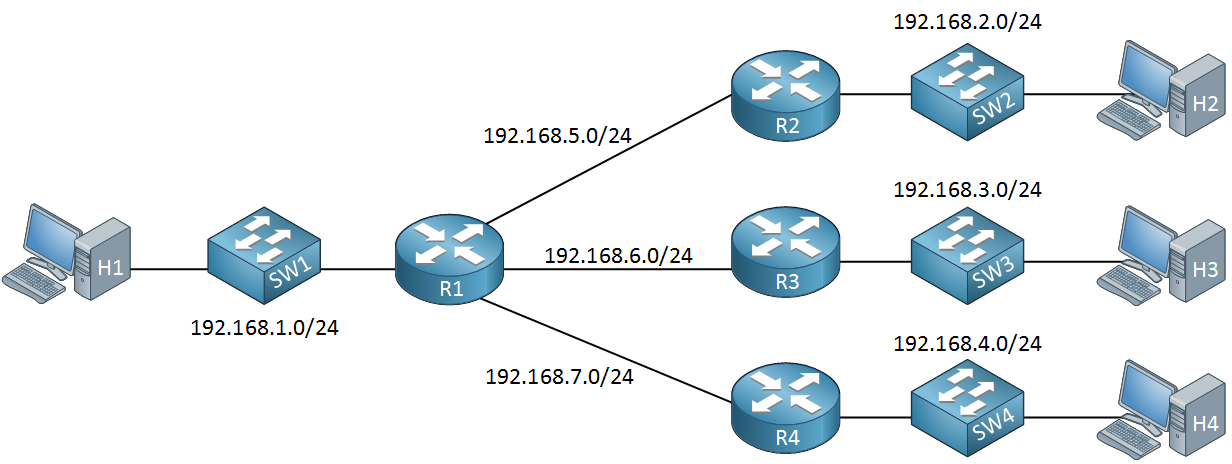
Given an address 192.168.1.0/24, its network will be:
- Network Address: 192.168.1.0
- First Host Address: 192.168.1.1
- Last Host Address: 192.168.1.254
- Broadcast Address: 192.168.1.255
Classless Subnetting Link to heading
Abbreviation note: n=network, h=host
Subnetting a Class C (/24) Network Link to heading
| CIDR Prefix | Subnet Mask | Subnet Mask in Binary | # Subnets | # Hosts |
|---|---|---|---|---|
| /25 | 255.255.255.128 | nnnnnnnn.nnnnnnnn.nnnnnnnn.nhhhhhhh 11111111.11111111.11111111.10000000 | 2 | 128 |
| /26 | 255.255.255.192 | nnnnnnnn.nnnnnnnn.nnnnnnnn.nnhhhhhh 11111111.11111111.11111111.11000000 | 4 | 64 |
| /27 | 255.255.255.224 | nnnnnnnn.nnnnnnnn.nnnnnnnn.nnnhhhhh 11111111.11111111.11111111.11100000 | 8 | 32 |
| /28 | 255.255.255.240 | nnnnnnnn.nnnnnnnn.nnnnnnnn.nnnnhhhh 11111111.11111111.11111111.11110000 | 16 | 16 |
| /29 | 255.255.255.248 | nnnnnnnn.nnnnnnnn.nnnnnnnn.nnnnnhhh 11111111.11111111.11111111.11111000 | 32 | 8 |
| /30 | 255.255.255.252 | nnnnnnnn.nnnnnnnn.nnnnnnnn.nnnnnnhh 11111111.11111111.11111111.11111100 | 64 | 4 |
| /31 | 255.255.255.254 | nnnnnnnn.nnnnnnnn.nnnnnnnn.nnnnnnhh 11111111.11111111.11111111.11111100 | 128 | 2 |
Subnetting a Class B (/16) Network Link to heading
| CIDR Prefix | Subnet Mask | Subnet Mask in Binary | # Subnets | # Hosts |
|---|---|---|---|---|
| /17 | 255.255.128.0 | nnnnnnnn.nnnnnnnn.nhhhhhhh.hhhhhhhh 11111111.11111111.10000000.00000000 | 2 | 32,768 |
| /18 | 255.255.192.0 | nnnnnnnn.nnnnnnnn.nnhhhhhh.hhhhhhhh 11111111.11111111.11000000.00000000 | 4 | 16,384 |
| /19 | 255.255.224.0 | nnnnnnnn.nnnnnnnn.nnnhhhhh.hhhhhhhh 11111111.11111111.11100000.00000000 | 8 | 8,192 |
| /20 | 255.255.240.0 | nnnnnnnn.nnnnnnnn.nnnnhhhh.hhhhhhhh 11111111.11111111.11110000.00000000 | 16 | 4,096 |
| /21 | 255.255.248.0 | nnnnnnnn.nnnnnnnn.nnnnnhhh.hhhhhhhh 11111111.11111111.11111000.00000000 | 32 | 2,048 |
| /22 | 255.255.252.0 | nnnnnnnn.nnnnnnnn.nnnnnnhh.hhhhhhhh 11111111.11111111.11111100.00000000 | 64 | 1,024 |
| /23 | 255.255.254.0 | nnnnnnnn.nnnnnnnn.nnnnnnhh.hhhhhhhh 11111111.11111111.11111100.00000000 | 128 | 512 |
Subnetting a Class A (/8) Network Link to heading
| CIDR Prefix | Subnet Mask | Subnet Mask in Binary | # Subnets | # Hosts |
|---|---|---|---|---|
| /9 | 255.128.0.0 | nnnnnnnn.nhhhhhhh.nnnnnnnn.hhhhhhhh 11111111.10000000.11111111.00000000 | 2 | 8,388,608 |
| /10 | 255.192.0.0 | nnnnnnnn.nnhhhhhh.nnnnnnnn.hhhhhhhh 11111111.11000000.11111111.00000000 | 4 | 4,194,304 |
| /11 | 255.224.0.0 | nnnnnnnn.nnnhhhhh.nnnnnnnn.hhhhhhhh 11111111.11100000.11111111.00000000 | 8 | 2,097,152 |
| /12 | 255.240.0.0 | nnnnnnnn.nnnnhhhh.nnnnnnnn.hhhhhhhh 11111111.11110000.11111111.00000000 | 16 | 1,048,574 |
| /13 | 255.248.0.0 | nnnnnnnn.nnnnnhhh.nnnnnnnn.hhhhhhhh 11111111.11111000.11111111.00000000 | 32 | 524,288 |
| /14 | 255.252.0.0 | nnnnnnnn.nnnnnnhh.nnnnnnnn.hhhhhhhh 11111111.11111100.11111111.00000000 | 64 | 262,144 |
| /15 | 255.254.0.0 | nnnnnnnn.nnnnnnhh.nnnnnnnn.hhhhhhhh 11111111.11111100.11111111.00000000 | 128 | 131,072 |
Example Link to heading
To divide the 192.168.1.0/24 network into two equal subnetworks (e.g., network A and network B), borrow one host bit to obtain the /25 network.
- Since it leaves 7 bits for hosts, it allows for 27 = 128 IP addresses in a single network.
- Two of these are reserved for the network address (first address) and the broadcast address (last address).
- Thus, the number of usable hosts per network is 27 – 2 = 126 IP addresses.
Network A (128 hosts):
- Network Address: 192.168.1.0
- First Available Host Address: 192.168.1.1
- Last Available Host Address: 192.168.1.126
- Broadcast Address: 192.168.1.127
Network B (128 hosts):
- Network Address: 192.168.1.128
- First Available Host Address: 192.168.1.129
- Last Available Host Address: 192.168.1.254
- Broadcast Address: 192.168.1.255
By knowing one network address and the magic number, we can explore all other addresses in the network:
- Network address of the next network is exactly 128, called the magic number, after the previous network address.
- The previous network’s first available host address is one host after its network address.
- The previous network’s broadcast address is one host before the next network address.
- The previous network’s last available host address is one host before its broadcast address.
Variable-Length Subnet Masks (VLSMs) Link to heading
- Consider a Class C network that uses /28, there will be 16 subnets of equal size, each with 14 usable IP addresses. If one of the subnet is a point-to-point network, which needs only two IP addresses, 12 IP addresses are wasted.
- This problem scales further with Class B and Class A address spaces.
- With VLSMs, small LANs can use /28 subnets with 14 hosts, and larger LANs can use /23 and /22 masks with 510 and 1022 hosts, respectively. Point-to-point networks can use a /30 mask which provides two hosts.
Best practice is to divide large networks into smaller subnets that can be assigned to sites. Further divide each site subnet into smaller subnets for data, VoIP, wireless LAN, and other subnets to be used in site VLANs. Furthermore, router/switch loopback addresses, WAN, and point-to-point links are also allocated separate IP subnets.
Simple Demonstration Link to heading
The goal is to divide the network 192.168.1.0/24 into three unequal subnets:
- 1 the size of 125 hosts
- 1 the size of 8 hosts
- 1 the size of 220 hosts
Although the default subnet mask is /24 (class C network), in order to house this number of hosts (220+125+8=353 hosts), the /23 network is required as the network size is doubled (510 usable hosts in total).
- Available address space: 192.168.1.0 - 192.168.2.255
Network A (220 hosts): 192.168.1.0/24 ➡ provides 254 usable hosts
- Network Address: 192.168.1.0
- First Available Host Address: 192.168.1.1
- Last Available Host Address: 192.168.1.254
- Broadcast Address: 192.168.1.255
Network B (125 hosts): 192.168.2.0/25 ➡ provides 126 usable hosts
- Network Address: 192.168.2.0
- First Available Host Address: 192.168.2.1
- Last Available Host Address: 192.168.2.126
- Broadcast Address: 192.168.2.127
Network C (8 hosts): 192.168.2.128/29 ➡ provides 8 usable hosts
- Network Address: 192.168.2.128
- First Available Host Address: 192.168.2.129
- Last Available Host Address: 192.168.2.134
- Broadcast Address: 192.168.2.135
As a result, the [super]network 192.168.1.0/24 summarises three [sub]networks: 192.168.1.0/24, 192.168.2.0/24, and 192.168.2.128/29.
VLSM in Action Link to heading
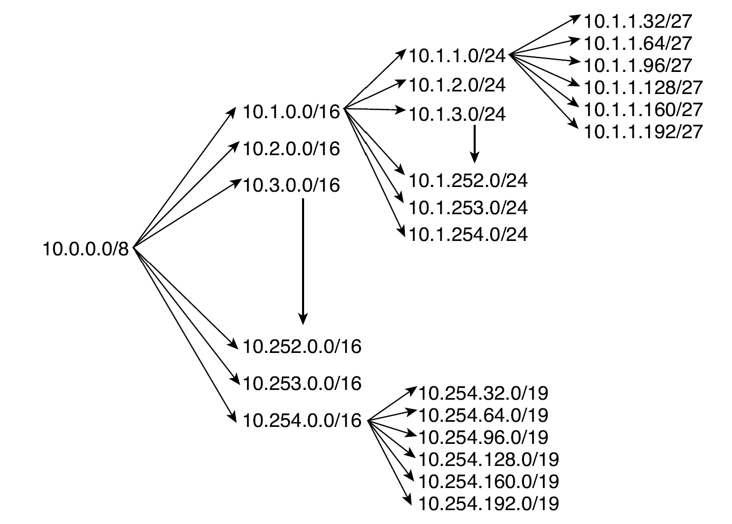
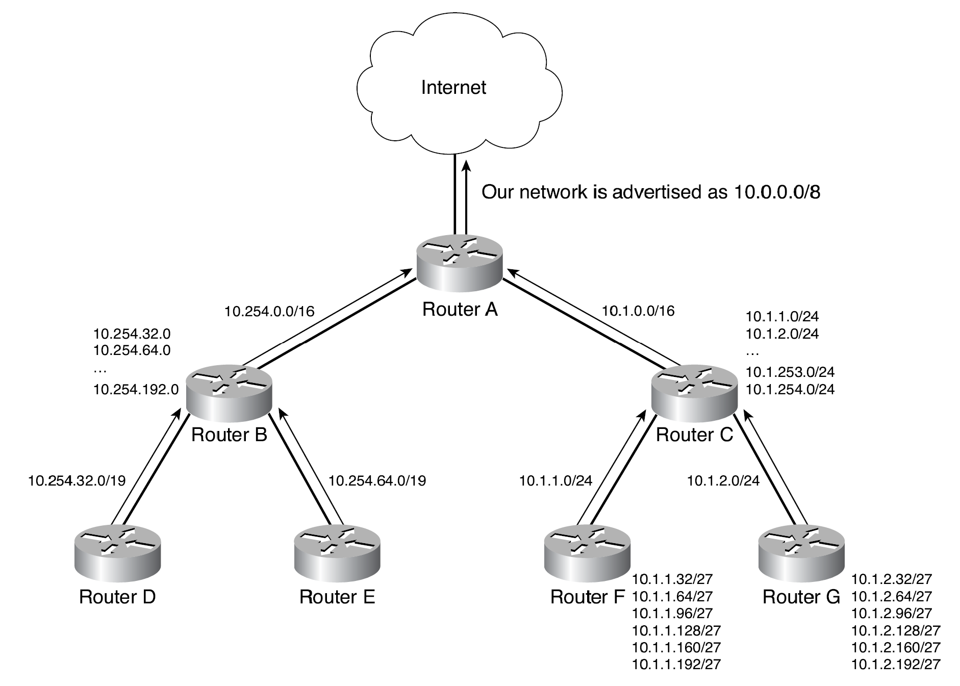
The figure below illustrates how a planned and thoughtful allocation of VLSM can reduce the size of an organisation’s routing tables and conserve IP address space.
- Notice how Routers F and G are able to summarise the six subnets behind them into a single advertisement (10.1.1.0/24 and 10.1.2.0/24, respectively) and how Router B (10.254.0.0/26) is able to aggregate all the subnets behind it into a single advertisement. Likewise, Router C is able to summarise the six subnets behind it into a single advertisement (10.1.0.0/16).
- Finally, the subnet structure is not visible outside of the organisation, because through the use of VLSM and aggregation, Router A injects a single route into the global Internet’s routing table (10.0.0.0/8).


Supernet or Supernetwork Link to heading
- Multiple IP addresses must share the same high-order bit to be properly summarised.
- Summarising a block of addresses is useful when designing IP Addressing Schemes for contiguous networks with multiple physical locations.
- For example, two network addresses 192.168.0.0/24 and 192.168.1.0/24 can be summarised as one singular network as 192.168.0.0/23.
Supernetting Link to heading
- Write out the networks needs summarising in binary format.
- 172.20.0.0 – 10101100.00010100.0.0
- 172.21.0.0 – 10101100.00010101.0.0
- 172.22.0.0 – 10101100.00010110.0.0
- 172.23.0.0 – 10101100.00010111.0.0
- Count the number of far-left consecutively matching bits to determine the
new subnet mask.
- 14 matching bits, /14 or 255.252.0.0
- Copy the matching bits and add all zero bits to the end to determine the new
network address.
- 10101100.00010100.00000000.00000000
- 172.20.0.0/14
Subnetting versus Supernetting Link to heading
| Term | Description |
|---|---|
| Subnetting | increase the prefix size to the right to enable very specific routes. |
| Supernetting | reduce the prefix size to the left to enable very general or summarised routes. |
IP Addressing Design Considerations Link to heading
- Number of locations
- Number of devices per location
- IP addressing requirements for each individual location or building:
- Number of devices to be supported in each communication closet
- Site requirements: data networks, wireless LANs, IP Telephony (IPT) networks, CCTV networks (security cameras), video conference systems, access control systems, network management, server farms, point-to-point links, and router/switch loopback addresses.
- Subnet size
| Title | Reference |
|---|---|
| Guidelines for Management of IP Address Space | RFC 1466 |
| Internet Registry IP Allocation Guidelines | RFC 2050 |