Table of Contents Link to heading
- Internet Protocol (IP)
- IPv4 Packet Header
- Size
- Fields
- Version (4 bits)
- Internet Header Length (IHL) (4 bits)
- Type of Service (ToS) or Differentiated Services (DiffServ/DS) (8 bits)
- Total Length (16 bits)
- Identification (16 bits)
- Fragment Offset and Flags (16 bits)
- IP Source Address (32 bits)
- IP Destination Address (32 bits)
- Time to Live (TTL) (8 bits)
- Protocol (8 bits)
- Header Checksum (16 bits)
- Options (variable length)
- Padding (variable length)
- IPv6 Packet Header
- IPv4 Addressing
- IPv6 Addressing
- Integration of IPv4 and IPv6
Internet Protocol (IP) Link to heading
IP was not designed to track and manage the flow of packets. These functions, if required, are performed by other protocols at other layers, primarily TCP at L4.
IP Version 4 (IPv4) Link to heading
IPv4 has three basic characteristics:
Connectionless Link to heading
In contrast, TCP, whose reliability comes from being connection oriented, establishes a connection between the sender and the receiver to exchange control data and ensure reliability of packet delivery.
IP simply sends packets without informing the receiver. Lacking a connection is not a problem for IP and is part of the “best effort” design. This is why IP and TCP work together so well in a TCP/IP protocol stack: If a packet is lost or late, TCP will correct the problem at L4, and IP can work more efficiently at L3.
Since IP does not have to be accountable for reliability or keep a connection, it uses much less processing power and bandwidth, called overhead, than TCP.
Best Effort Link to heading
In this case, TCP can be relied on to inform the sender of delivery problems.
The TCP segment contains information that allows the receiver to communicate with the sender to request a retransmission if packets cannot be received.
Media Independent Link to heading
The arrangement of bits in the IP packet and IP header will not be changed as the packet transfers from wireless to any other physical media.
IP Version 6 (IPv6) Link to heading
The services provided by IP, as well as the packet header structure and contents, are specified by either IPv4 or IPv6.
IPv6 routing is disabled by default and must be enabled manually.
- Note: By default, the 3650 supports IPv6 interface configuration.
Switch(config)# ipv6 unicast-routing
To find more information about at IPv6, refer to the following RFCs:
| Title | Reference |
|---|---|
| IPv6 Specification | RFC 2460 |
| IPv6 Addressing Architecture | RFC 3513 |
| Security Architecture for the IP | RFC 2401 |
| The Addition of Explicit Congestion Notification (ECN) to IP | RFC 3168 |
| IP Authentication Header | RFC 4302 |
| ICMPv6 for the IPv6 Specification | RFC 4443 |
IPv6, compared to IPv4, has the following improvements:
Increasing Address Space Link to heading
Improving Packet Handling Link to heading
Eliminating the Need for NAT Link to heading
IPv4 Packet Header Link to heading

Image Source: The Third Internet
Size Link to heading
Fields Link to heading
Version (4 bits) Link to heading
A version binary value set to 0100 identifies an IPv4 packet.
Internet Header Length (IHL) (4 bits) Link to heading
The length is not always the same because of variable data in the Options field.
Type of Service (ToS) or Differentiated Services (DiffServ/DS) (8 bits) Link to heading
For example, a packet containing IP voice data gets precedence over a packet containing streaming music. The way a router handles a packet from this data is known as QoS.
Total Length (16 bits) Link to heading
The minimum length of a packet is 20 bytes (header with no data), and the maximum length with data is 65,535 bytes.
Identification (16 bits) Link to heading
Fragment Offset and Flags (16 bits) Link to heading
Fragment Offset (13 bits) Link to heading
Flags (3 bits) Link to heading
Don’t Fragment (DF) Flag (1 bit) Link to heading
If a router still needs to fragment a packet but the DF flag bit is set, the router will discard this packet.
More Fragments (MF) Flag (1 bit) Link to heading
When a receiving host sees a packet arrive with the MF flag set to 1, it examines the Fragment Offset to see where this fragment is to be placed in the reconstructed packet.
When a receiving host receives a frame with the MF flag bit set to 0 and a non-zero value in the Fragment offset, it places that fragment as the last part of the reconstructed packet.
An unfragmented packet has all zero fragmentation information:
- MF flag = 0
- Fragment offset = 0
IP Source Address (32 bits) Link to heading
Routers will use this data to forward the packet to the correct network.
The source IPv4 address is always a unicast address.
IP Destination Address (32 bits) Link to heading
Routers will use this data to forward the packet to the correct network.
The destination IPv4 address is a unicast, multicast, or broadcast address.
Time to Live (TTL) (8 bits) Link to heading
Each router that handles the packet decrements the TTL field by at least 1. The packet will be dropped if the TTL value reaches 0. This keeps the Internet from being cluttered with lost packets.
Protocol (8 bits) Link to heading
Example values are:
- 01 ICMP
- 06 TCP
- 17 UDP
Header Checksum (16 bits) Link to heading
An algorithm is run by each router, and if the checksum is invalid, the packet is assumed to be corrupted and therefore dropped. Because the TTL value is changed by each router that handles the packet, the header checksum is recalculated at each hop.
Options (variable length) Link to heading
Padding (variable length) Link to heading
IPv6 Packet Header Link to heading

Image Source: Networkel
Size Link to heading
Fields Link to heading
Version (4 bits) Link to heading
A version binary value set to 0110 identifies an IPv6 packet.
Traffic Class (8 bits) Link to heading
Flow Label (20 bits) Link to heading
Payload Length (16 bits) Link to heading
Next Header (8 bits) Link to heading
Hop Limit (8 bits) Link to heading
When the counter reaches 0, the packet is discarded, and an ICMPv6 Time Exceeded message is forwarded to the sending host, indicating that the packet did not reach its destination because the hop limit was exceeded.
Source IPv6 Address (128 bits) Link to heading
Destination IPv6 Address (128 bits) Link to heading
IPv4 Addressing Link to heading
Format Link to heading
Representation Link to heading
Each octet in the 32-bit IPv4 address is converted from binary to a decimal number between 0 (0000 0000) and 255 (1111 1111).
For example, an IPv4 address 10011101.10010001.11111011.01101110 can be displayed as 157.145.251.110.
Classful Addressing Link to heading
| Address Class | First Octet Range | Prefix and Mask | # Possible Networks | # Usable Hosts per Network | Common Usage |
|---|---|---|---|---|---|
| A | 1 to 127 | /8 255.0.0.0 | 126 (27) | 16,777,214 (224-2) | Extremely large networks |
| B | 128 to 191 | /16 255.255.0.0 | 16,382 (214) | 65,534 (216-2) | Moderate- to large-size networks |
| C | 192 to 223 | /24 255.255.255.0 | 2,097,150 (221) | 254 (28-2) | Small networks |
| D | 224 to 239 | /4 240.0.0.0 | - | - | Multicast applications |
| E | 240 to 255 | /4 240.0.0.0 | - | - | Future use reservation |
Classless Addressing Link to heading
Classless Interdomain Routing (CIDR) Link to heading
- Enables continuous, uninterrupted growth of large networks.
- Allows several IP networks appear to networks outside the group as a single, larger entity.
- Eliminates the concept of Class A, B, and C networks and replaces this concept with a generalised IP prefix.
- Reduces the local administrative burden of updating external route information since only a smaller number of routes are advertised.
- Reduces route-flapping and convergence issues.
- A flapping route is going up and down, up and down, over and over again, causing serious performance problems.
- If one route within a summarised route is flapping, this will not affect the status of the summarised route and thus will not impact many of the routers in the network.
- Reduces CPU and memory load on a router as the routing table is populated with fewer entries.
- Increases efficiency in the use of available address space.
- Enables the delegation of network numbers to customers or other portions of the network.
Subnetting Link to heading
Major Reserved and Special-Purpose IPv4 Addresses Link to heading
| Present Use | CIDR Prefix | Reference |
|---|---|---|
| Default route | 0.0.0.0 /8 | RFC 1700, Page 4 |
| Private-use class A addresses | 10.0.0.0 /8 | RFC 1918 |
| Public-data networks | 14.0.0.0 /8 | RFC 1700, Page 181 |
| Cable television networks | 24.0.0.0 /8 | - |
| Reserved but subject to allocation | 39.0.0.0 /8 | RFC 1797 |
| Shared address space | 100.64.0.0 /10 | RFC 6598 |
| Loopback addresses | 127.0.0.0 /8 | RFC 1700, Page 5 |
| Reserved but subject to allocation | 128.0.0.0 /16 | - |
| Link-local addresses | 169.254.0.0 /16 | RFC 3927 |
| Private-use class B addresses | 172.16.0.0 /12 | RFC 1918 |
| IETF protocol assignments | 192.0.0.0 /24 | RFC 5736 |
| Test-net | 192.0.2.0 /24 | RFC 5735 |
| 6to4 relay anycast addresses | 192.88.99.0 /24 | RFC 3068 |
| Private-use class C addresses | 192.168.0.0 /16 | RFC 1918 |
| Network interconnect device benchmark testing | 192.18.0.0 /15 | RFC 2544 |
| Reserved but subject to allocation | 223.255.255.0 /24 | - |
| Multicast (class D) | 224.0.0.0 /4 | RFC 1112 RFC 3171 |
| Reserved for future use (class E) | 240.0.0.0 /4 | RFC 1700, Page 4 |
| Limited broadcast | 255.255.255.255 /32 | RFC 919, Section 7 RFC 922, Section 7 |
Private Addresses Link to heading
RFC 1918 sets aside three blocks of IP addresses for private or internal use. Addresses in one of these ranges are not routed on the Internet backbone. Internet routers immediately discard private addresses.
| Class | RFC 1918 Internal Address Range | CIDR Prefix |
|---|---|---|
| A | 10.0.0.0 to 10.255.255.255 | 10.0.0.0 /8 |
| B | 172.16.0.0 to 172.31.255.255 | 172.16.0.0 /12 |
| C | 192.168.0.0 to 192.168.255.255 | 192.168.0.0 /16 |
Multicast (Class D) Link to heading
Hosts that want to receive particular multicast data are called multicast clients. The multicast clients use services initiated by a client program to subscribe to the multicast group.
The following are some examples of multicast transmission:
- Video and audio broadcasts
- Routing information exchange by some routing protocols
- Distribution of software
- News feeds
The IPv4 addresses from 224.0.0.0 to 239.255.255.255 are reserved for multicast communication. This multicast address range is subdivided into different types of addresses:
- Reserved link-local addresses
- 224.0.0.0 /24 (224.0.0.0 to 224.0.0.255)
- Used for multicast groups on a local network
- A typical usage is in routing protocols using multicast transmission to exchange routing information
- Globally scoped addresses
- 224.0.1.0 to 238.255.255.255
- Used to multicast data across the Internet
- For example, 224.0.1.1 has been reserved for NTP to synchronise the time-of-day clocks of network devices
- Administratively scoped addresses (also called limited-scope addresses)
Default Route Link to heading
The use of this address also reserves all addresses in the 0.0.0.0 /8 address block (0.0.0.0–0.255.255.255).
Loopback Addresses Link to heading
The loopback address creates a shortcut method for TCP/IP applications and services that run on the same device to communicate with one another.
By using the loopback address instead of the assigned IPv4 host address, two services on the same host can bypass the lower layers of the TCP/IP stack.
A user can ping the loopback address to test the configuration of TCP/IP on the local host.
Although only the single 127.0.0.1 address is used, address block 127.0.0.0 /8 (127.0.0.0 to 127.255.255.255) is reserved. Any address within this block will loop back within the local host. No address within this block should ever appear on any network.
Link-Local Addresses Link to heading
Communication using IPv4 link-local addresses is only suitable for communication with other devices connected to the same network. A host must not send a packet with an IPv4 link-local destination address to any router for forwarding and should set the IPv4 TTL for these packets to 1.
Client/server and peer-to-peer applications will work properly with IPv4 link-local addresses on the local network.
Test-Net Addresses Link to heading
Unlike the experimental addresses, network devices will accept the test-net addresses in their configurations. You can often find these addresses used with the domain names example.com or example.net in RFCs and vendor and protocol documentation. Addresses within this block should not appear on the Internet.
IPv6 Addressing Link to heading
Format Link to heading
Every four bits is represented by a single hexadecimal digit; for a total of 32 hexadecimal digits (128 bits). Thus, every octet contains two hexadecimal digits.
Representation Link to heading
Each hextet in the 128-bit IPv6 address is converted from binary or hexadecimal to a decimal number between 0 (0000 0000 0000 0000 or 0x0000) and 65,535 (1111 1111 1111 1111 or 0xFFFF).
For example, an IPv6 address 10011101.10000010.00010010.10010010.00011101.00111011.10001101.11110001.00111011.11000111.11000011.10001110.11001111.00001111.00111110.00001110 can be displayed as 9D82:1292:1D3B:8DF1:3BC7:C38E:CF0F:3E0E.
When working with IPv6 address, it takes a lot to write an address of 128 bits long. Thus, to make life simpler, the following two rules are used to condense this notation:
Omit Leading Zeros Link to heading
This rule only applies to leading zeros, not to trailing zeros, otherwise the address would be ambiguous. For example, the hextet “ABC” could be either “0ABC” or “ABC0”, but these do not represent the same value.
Omit All Zero Segments Link to heading
::, but this can be done only
once per address.An unknown or unspecified address is typed as all zeros, so it can be
represented in IPv6 as ::.
Examples of IPv6 Address Reduction Link to heading
| Full | Abbreviation |
|---|---|
| FF01:0000:0000:0000:0000:0000:0000:0001 | FF01::1 |
| 2031:0000:130F:0000:0000:09C0:876A:130B | 2031:0:130F::9C0:876A:130B |
| 0000:0000:0000:0000:0000:0000:0000:0001 | ::1 |
| FE80:0000:0000:5EFE:0192.0168.0001.0123 | FE80::5EFE:192.168.1.123 |
| FE80:0000:0000:0000:1585:4868:495F:D521 | FE80::1585:4868:495F:D521 |
Prefix Length Link to heading
The prefix length can range from 0 to 128. A typical IPv6 prefix length for LANs and most other types of networks is /64. This means the prefix or network portion of the address is 64 bits in length, leaving another 64 bits for the interface ID (host portion) of the address.
The term Interface ID is used because a single host may have multiple interfaces, each having one or more IPv6 addresses. It is highly recommended that in most cases /64 subnets should be used.
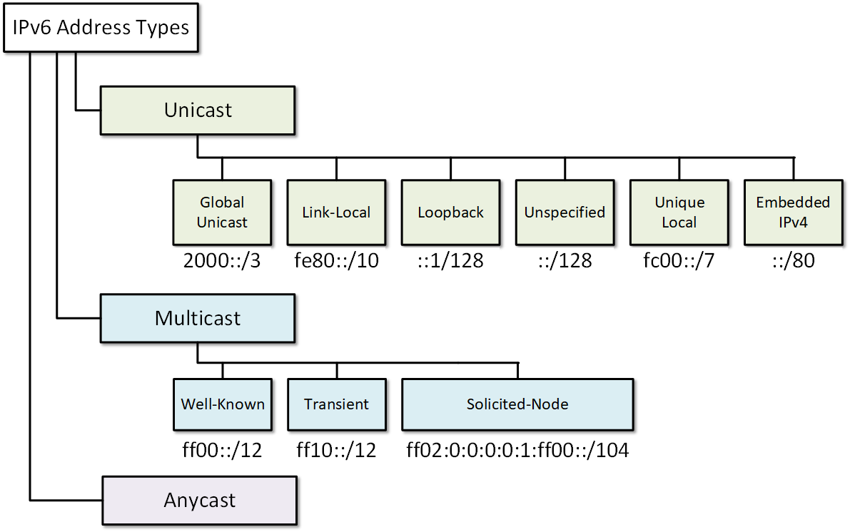
Types of IPv6 Addresses Link to heading
Unlike IPv4, IPv6 does not have a broadcast address. Broadcast functionality is implemented using all-nodes multicast addresses.
Unicast Link to heading
When configuring network interfaces for IPv6, a single network interface could have a number of addresses associated with it. This may be a mixture of these address types. Within the unicast type there are three main address groups:
Global Unicast Link to heading
They represent about one-eighth of all IPv6 addresses, and the numbers are handed out by the IANA, as they are with IPv4.
They can be configured statically or assigned dynamically.
Static Addressing Link to heading
IPv6 static addressing works exactly the same as IPv4 static addressing, with
the exception of swapping ip for ipv6.
IPv6 provides two different ways of implementing DHCP, either stateful or stateless. Static addressing with DHCPv6 (stateless) - a stateless service means there is no server that maintains network address information. Therefore, it does not track what information is given out to clients and does not give out IPv6 addresses; instead, it provides the extra information that most people relate with typical DHCP assignment (e.g. DNS server information). Stateless DHCP is then matched up with another mechanism (such as static addressing or SLAAC) for IPv6 address assignment.
Dynamic Addressing Link to heading
Dynamic addressing via DHCPv6 (stateful) is responsible for assigning IP addresses to clients. Being a stateful service, DHCP server keeps a record of all clients and the IPv6 address assigned to them.
When DHCPv6 or SLAAC is used, the local router’s link-local address will automatically be specified as the default gateway address.
Stateless Address Autoconfiguration (SLAAC) Link to heading
By default, RA messages are sent out periodically by most IPV6 routers and include:
- One or more IPv6 prefixes (Link-local scope)
- Prefix lifetime information
- Flag information
- Default device information (Default router to use and its lifetime)
SLAAC is implemented on the IPv6 client by listening for these local RA’s and then taking the prefix that is advertised to form a unique address that can be used on the network. For this to work, the prefix that is advertised must advertise a prefix length of 64 bits (i.e. /64); SLAAC will then dynamically form a host identifier that is 64 bits long and will be suffixed to the end of the advertised prefix to form an IPv6 address.
Originally, the host identifier was formed using the EUI-64 rules (the same that are used to form link local addresses) and many devices still use this method. However, some Microsoft operating systems by default do not use this original method. Instead, they take advantage of some additional privacy extensions that were defined in RFC4941.
EUI-64 Conversion Process Link to heading
- Split the MAC (48-bit) address into two 3-byte (24-bit) halves
- Insert FFEE (the missing 16 bits) in the middle
- Invert the 7th bit
- Change the address from a globally unique to a locally administered address
- This is the U/L bit (universal/local)
- Router R1:
- IPv6 address - 2000:1234:5678::1001:1/64
- Advertised IPv6 prefix - 2000:1234:5678::/64
- Client PC1:
- MAC address - 0200:1234:5678
The prefix 2000:1234:5678::/64 will be learned from R1’s RA messages and will be the initial prefix. The client identifier would then be created from the MAC address assigned to PC1, in this case 0200:1234:5678.
- Split the MAC address and put FFEE in the middle
- 0200:12FF:FE34:5678
- Invert the 7th bit
- The first byte is 00000010 (0x02)
- Will become 00000000 (0x00)
- 0000:12FF:FE34:5678
When the prefix and the host identifier are brought together, it results in an IPv6 address that is used for PC1 of 2000:1234:5678:0000:0000:12FF:FE34:5678, which can be shortened to 2000:1234:5678::12FF:FE34:5678.
Quick Inversion of the Seventh Bit Link to heading
| Column 1 | Column 2 |
|---|---|
| 0 | 2 |
| 1 | 3 |
| 4 | 6 |
| 5 | 7 |
| 8 | A |
| 9 | B |
| C | E |
| D | F |
Reserved Addresses Link to heading
This reserved space amounts to approximately 1 of every 256 IPv6 addresses.
| Present Use | CIDR Prefix | # Addresses | Reference |
|---|---|---|---|
| Default route | ::/0 | 2128 | RFC 1700 |
| Unspecified address | ::/128 | 1 | RFC 4291 |
| Loopback address | ::1/128 | 1 | RFC 4291 |
| IPv4-mapped addresses | ::ffff:0:0/96 | 2128 − 96 = 232 = 4,294,967,296 | RFC 4291 |
| IPv4 translated addresses | ::ffff:0:0:0/96 | 232 | RFC 4291 |
| IPv4/IPv6 translation (global Internet) | 64:ff9b::/96 | 232, with 2128 for each IPv4 | RFC 6052 |
| IPv4/IPv6 translation (private internets) | 64:ff9b:1::/48 | 242, with 280 for each IPv4 | RFC 8215 |
| Discard prefix | 100::/64 | 264 | RFC 6666 |
| Teredo tunnelling | 2001::/32 | 296 | RFC 4380 RFC 8190 |
| Port Control Protocol (PCP) anycast address | 2001:1::1/128 | 1 | RFC 7723 |
| ORCHIDv2 | 2001:20::/28 | 2100 | RFC 7343 |
| Addresses used in documentation and example source code | 2001:db8::/32 | 296 | RFC 3849 |
| 6to4 | 2002::/16 | 2112 | RFC 3056 |
| Unique-local addresses | fc00::/7 | 2121 | RFC 4193 RFC 8190 |
| Link-local addresses | fe80::/64 from fe80::/10 | 264 | RFC 4291 |
| Multicast addresses | ff00::/8 | 2120 | RFC 1700 |
Private addresses Link to heading
Akin to IPv4, these addresses cannot be routed over the Internet.
There are two categories of private addresses:
Unique-local Addresses Link to heading
These addresses are in the range of FC00::/7 to FDFF::/7.
Unique local addresses can be used for devices that will never need or have access from another network.
Link-local Addresses Link to heading
These addresses all start with FE, and the third digit is 8, 9, A, or B, or FE80::/10.
All IPv6 within a given data link that have local-link addresses can talk to each other. No routers, internal or external, forward traffic to or from these addresses.
Link-local addresses are similar to the Automatic Private IP Addressing (APIPA), given that they are self-generated. If a link-local address is not configured manually on an interface, the device will automatically create its own without communicating with a DHCP server.
IPv6-enabled hosts create an IPv6 link-local address even if the device has not been assigned a global unicast IPv6 address.
Multicast Link to heading
IPv6 multicast addresses have the prefix FF00::/8.
Assigned Multicast Link to heading
Two common IPv6 assigned multicast groups include:
All-Nodes Multicast Group Link to heading
A packet sent to this group is received and processed by all IPv6 interfaces on the link or network. This has the same effect as a broadcast address in IPv4. The figure shows an example of communication using the all-nodes multicast address. An IPv6 router sends Internet Control Message Protocol version 6 (ICMPv6) Router Advertisement (RA) messages to the all-node multicast group. The RA message informs all IPv6-enabled devices on the network about addressing information, such as the prefix, prefix length, and default gateway.
All-Routers Multicast Group Link to heading
A router becomes a member of this group when it is enabled as an IPv6 router with the ipv6 unicast-routing global configuration command. A packet sent to this group is received and processed by all IPv6 routers on the link or network.
IPv6-enabled devices send ICMPv6 Router Solicitation (RS) messages to the all-routers multicast address. The RS message requests an RA message from the IPv6 router to assist the device in its address configuration.
Solicited-Node Multicast Link to heading
Anycast Link to heading
“Closest” typically means the one with the best routing metric according to the IPv6 routing protocol.
All Zeros versus All Ones Link to heading
The all-ones address can be used due to the fact that broadcast addresses are not used within IPv6.
The all-zeros address can also be used, but is reserved as a Subnet-Router anycast address, and should be assigned only to routers.
Integration of IPv4 and IPv6 Link to heading
To that goal, there are three basic methods of compatibility:
Dual-stack Link to heading
In this configuration, the device decides how to send the traffic based on the destination address of the other device.
To support dual-stack routing on a single interface, you need to configure IPv6 on your routing device. The following commands allow for forwarding of IPv6 data packets:
Router1(config)# interface ethernet0
Router1(config-if)# ip address 192.168.75.1 255.255.255.0
Router1(config-if)# ipv6 address 2123:AFFF::192:168:75:1/120
Tunnelling Link to heading
The four main types of tunnelling are
Manual IPv6-to-IPv4 Tunnelling Link to heading
So as to not fragment the packet from adding the IPv4 header to it, the data packet needs to be reduced by 20 bytes if the IPv4 has an optional protocol field, or 20 octets if it does not, as well as require routers support both IP stacks.