Table of Contents Link to heading
- Conceptual Modelling
- Conceptual Design
- Design Process
- Conceptual Modelling
- Entity-Relationship Model
- Unified Modelling Language Diagram
- UML Diagram Example
- Association
- Multiplicity
- Summary of Multiplicity Syntax
- Association Class
- Recursive Relationship or Self Association
- Aggregation
- Composition
- Strong and Weak Entity Type
- Inheritance
Conceptual Modelling Link to heading
Overall, Database requirements are collected and visualised as a UML diagram.
- Uses a higher-level language (4GL) to abstract away the complexities of implementation.
- A graphical way of conceptualising data capture requirements to ensure the required data is collected by the database design!
For example:

Conceptual Design Link to heading
When designing a database, we should:
- Create a list of all the real-world AND conceptual objects that we need to store data about.
- To each of those items, list all the attributes required to capture the desired data.
- Check that each of our objects only captures the relevant information to that object.
- Check to see if there are any Candidate Keys:
- Do they apply to all records in all cases?
- If so, pick the best one (usually the smallest one) as the Primary Key.
- If not, add an artificial PK - Surrogate Key.
- Draw associations lines between classes that describe interacting objects.
- E.g. Students interact with (attend) classes.
- Classes interact with (belong to) courses.
- Add multiplicity values to association lines.
- E.g. How many classes does a student enrol in?
- How many classes does a course have?
- Check that each class only records relative data and does not contain any repeating value, group and multi-value data.
- If not, separate into new classes and repeat the above steps 1-7 !!
Design Process Link to heading
Most database designs will use the Entity-Relationship (ER) model or Unified Modelling Language (UML) approach to start off with an acceptable design and then use the Normalisation technique to check the design for its efficiency and redundancy.
The design process contains five fundamental steps:
- Classes
- Attributes
- Relationships
- Multiplicity
- Again
Conceptual Modelling Link to heading
Database requirements are gathered and visualised as a UML diagram.
- Use a higher-level language (4GL) to abstract away the complexities of implementation.
- A graphical way of conceptualising data meeting the requirements to ensure the required data is gathered by the database design!
Entity-Relationship Model Link to heading
- Entities
- Reflect real-world and theoretical/conceptual objects.
- A real-world object is one that can be easily identifiable and
distinguishable.
- E.g., Book, Car, Staff, etc.
- A theoretical/conceptual object is one that is intangible/untouchable.
- E.g., Class, Course, Sale, etc.
- A real-world object is one that can be easily identifiable and
distinguishable.
- Represent what the database keeps track of.
- Translated into relations/tables in the final database.
- Some entities may be the result of relationships between other entities.
- E.g., StudentClasses, StudentCourses, CourseBooks, etc.
- To simplify, an entity corresponds to a class in Object-Oriented Programming
(OOP).
- A tuple within a relation corresponds to an instance of a class (an entity).
- An instance of a class is a collection of information stored in the database at a particular moment.
- Programming analogy: Each variable has a particular value at a given instant. The values of the variables in a program at a point in time correspond to an instance of an class.
- Relationships & Multiplicity
- Depict how many objects of one type interact with another.
- Attributes
- Describe details of an entity.
- Can also be used to help record entity interactions.
- Can include the domain (data
type, range of values).
- Every attribute requires a data type (int, varchar, etc.)
- Depending on the situation, it may not be necessary to include the range of values.
- E.g., studentName: varchar(100), favColour: varchar(10) {red, green, blue}.
Unified Modelling Language Diagram Link to heading
- A Class is equivalent to an entity (table or relation) in the proposed Relational Database.
- An Object is an instance of a class (e.g. a tuple within a relation)
- An Association is a relationship between two classes.
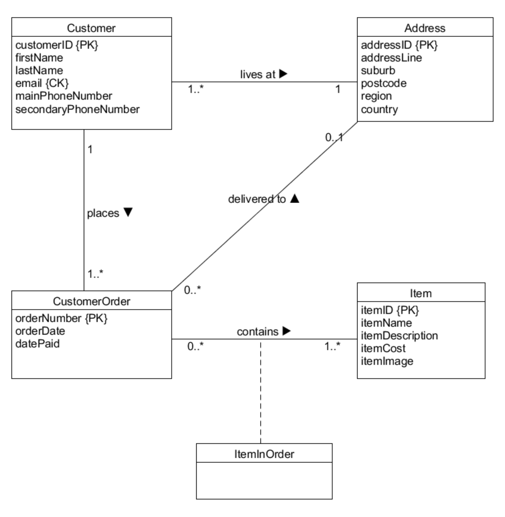
UML Diagram Example Link to heading

Association Link to heading
An Association captures the relationships between objects.
- If a student enrols in a course, we create an association line between the two classes and give it a description (or a role).
- This indicates that objects in the Student class can interact with objects in the Course class

Multiplicity Link to heading
The Multiplicity attribute of a relationship specifies the number of possible occurrences of an entity type that may relate to a single occurrence of an associated entity type through a given relationship.
Multiplicities represent business rules established by a user or company
- They do not necessarily modify the database design
- They are generally implemented at the application level/user interface

Participation identifies whether all or only some objects participate in a relationship (is it mandatory?)
- A course must have at least 10 students - (every course participates)
- A student may not enrol in any course (does not participate in “enrols”)
Cardinality indicates the maximum number of possible relationship occurrences for an entity participating in a relationship (how many times did it take place?)
- A course can have many students.
- A student maximally enrols in 5 courses.

Rules:
- No value or a 1 implies
1..1(1:1 relationship) - A single * implies
0..*
- One-to-One (
1:1)
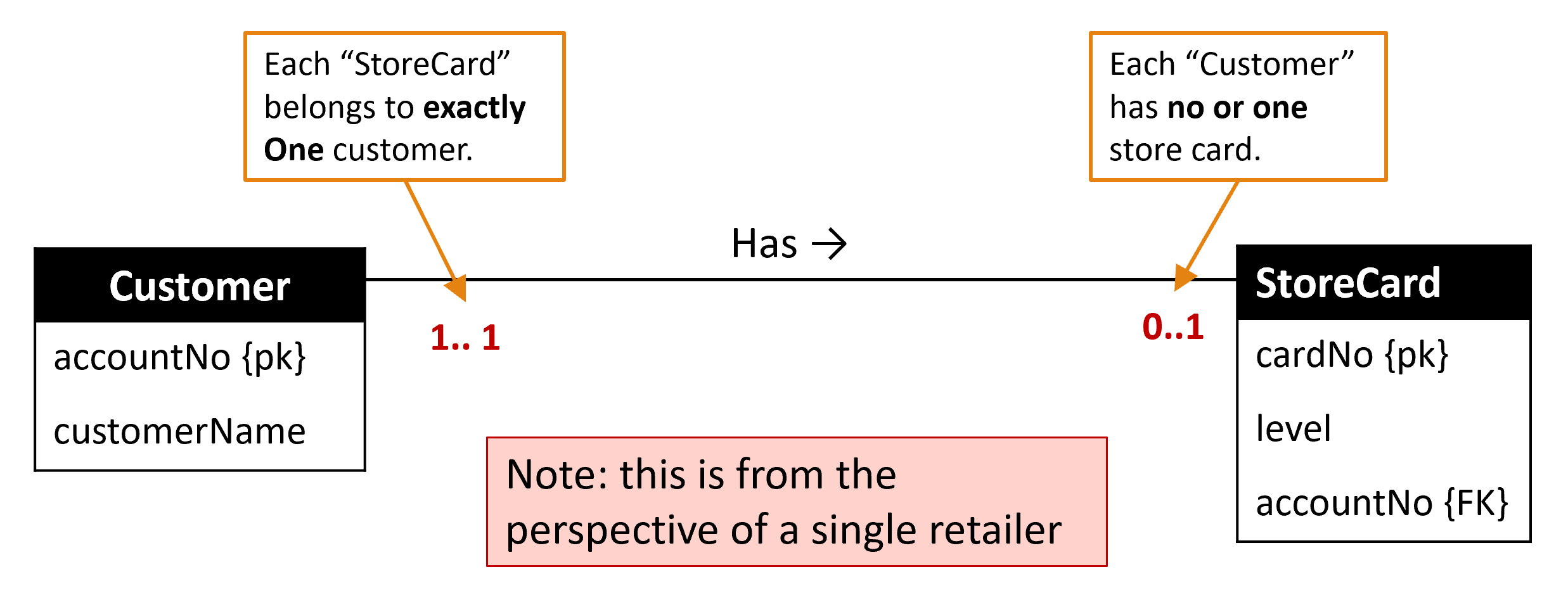
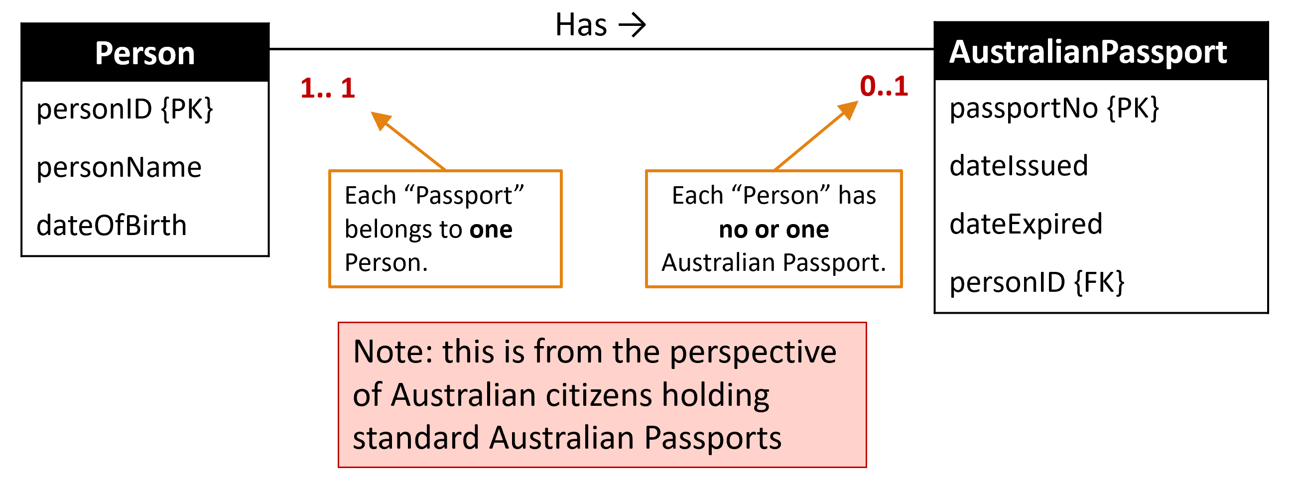
- Every object is associated with at most one of the other object.
- When we see this relationship, we need to put either of the PK into the
other table as a FK.
- It does not matter which way it goes.
- Nevertheless, in the case where there is one side that has the 0 occurence, then that side will store the FK referencing the other side’s PK.
- One-to-Many (
1:*) and Many-to-One (*:1)
- Many elements of one object are related to at most one of the other object.
- When we see this relationship, we need to put the PK of the one-side table to the many-side table as a FK.


- Many-to-Many (
*:*) or (0:*) or (m:n)
- No restriction on the relationship.
- When we see this relationship, we need to make an association table.
- This table stores the two main tables’ PKs as FKs.
- These FKs can also be the PKs of the association table.
- Thus, that two tables do not store each other’s PK.
- If an appropriate name cannot for the association table cannot be invented, then just use a combination of the two main tables.


Summary of Multiplicity Syntax Link to heading
| Syntax | Meaning |
|---|---|
0..1 | Zero or one entity occurence |
1..1 (or 1) | Exactly one entity occurrence |
0..* (or *) | Zero or many entity occurrences |
1..* | One or many entity occurences |
5..10 | Minimum of 5 up to a maximum of 10 entity occurrences |
0, 3, 6-8 | Zero or three or six, seven, or eight entity occurrences |
Note: No number at the end of a relationship means 1..1 or just 1.
Association Class Link to heading
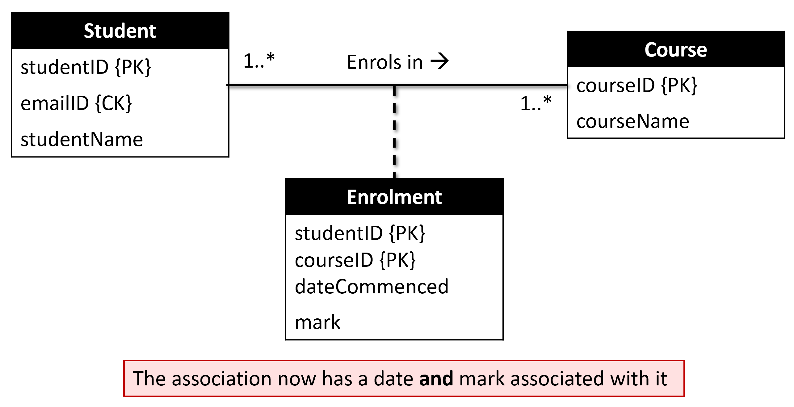
An Association Class allows attributes to be included with the association relationship.
For example, consider the below UML diagram:

In terms of the enrolment, what if we want to record the date commenced and mark they received at the end of the course?
- The association class captures the details of the association.
Recursive Relationship or Self Association Link to heading
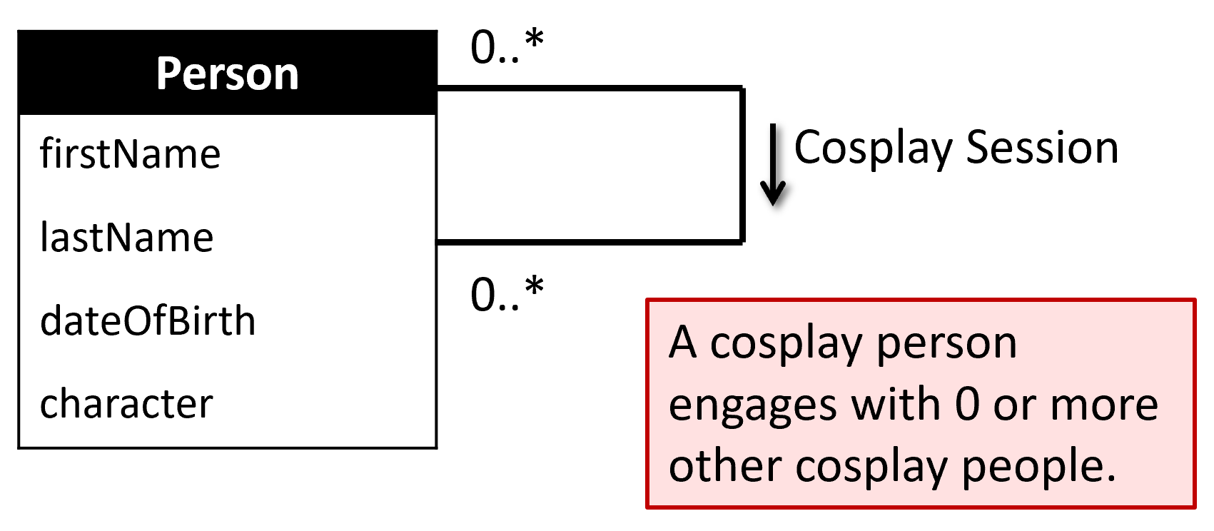
Similar to the concept of recursion in programming, a recursive relationship or self association is a class that associates itself.
The same entity type can participate more than once in different roles.
- However, role names should be used in a recursive relationship type to distinguish between each of these roles.

Aggregation Link to heading
Aggregation represents a has-a or is-part-of association between two entity types.
It is a conceptual notion that distinguishes a whole from its parts.
An unfilled diamond at the whole end denotes aggregation.
For example, a program is an aggregation of courses.
- A course is part of more than one program.
- Deleting a program does not delete the courses.

Composition Link to heading
Composition is a stronger notion, representing the lifetime of the parts is bound up with the whole.
A filled diamond at the whole end denotes composition.
For example, a foot is composed of five toes.
- Deleting the foot also takes the toes with it!

Strong and Weak Entity Type Link to heading
- Strong Entity Type is an entity that is not existence-dependent on some other entity type(s).
- For example:
- Student, Building, Competition
- All the previous examples (except Association Class)
- Weak Entity Type is an entity type that is existence-dependent on some other entity type(s).
- An instance cannot be uniquely identified by its attributes alone.
- For example:
- Week4Lecture (what subject, which semester, which year?)
- StudentAssignment (what subject, which semester?)
- CompetitionRound, BuildingRoom

Inheritance Link to heading
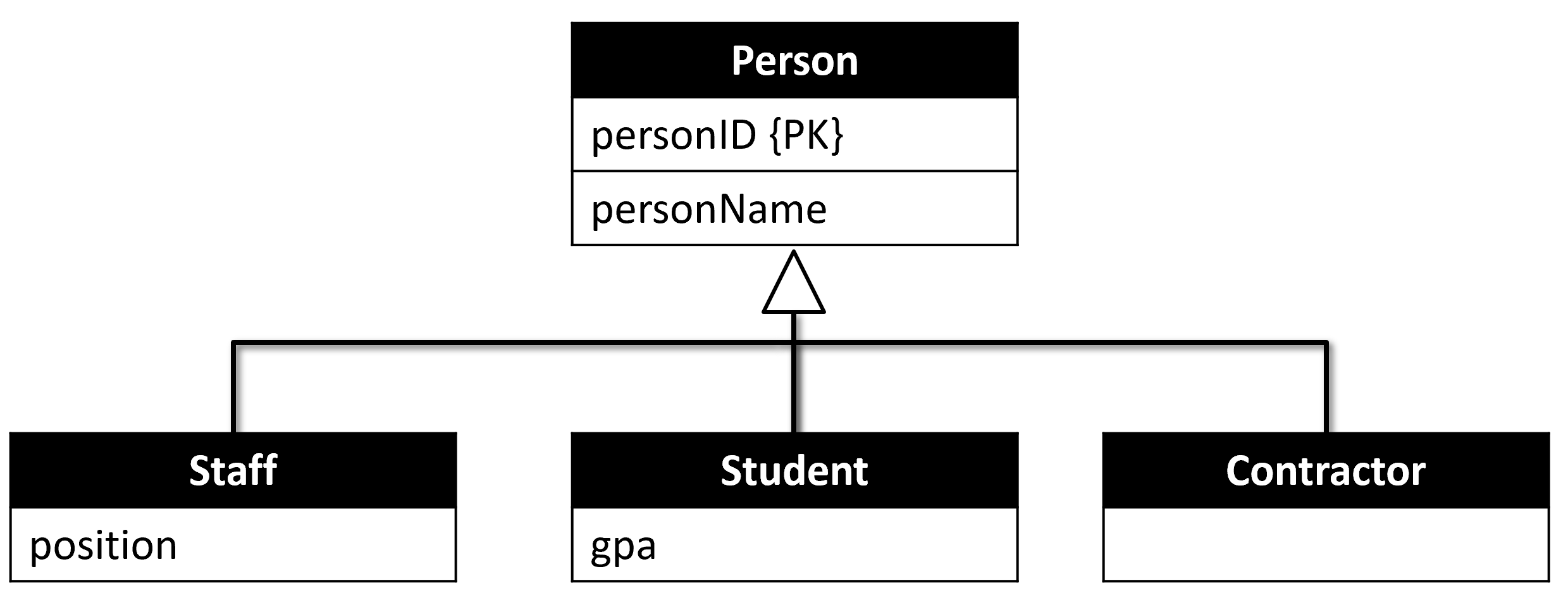
- Superclass
- An entity type that includes one or more distinct subgroups of its occurrences.
- E.g. Person(name)
- Subclass
- A subgroup of occurrences of an entity type
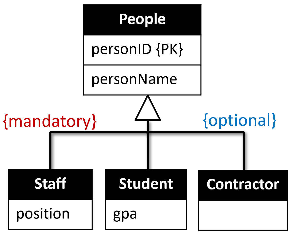
- E.g. Staff and Student are two subclasses of Person.
- Subclasses may or may not have any attribute of their own.
- Inheritance Hierarchy
- Also called a Generalisation/Specialisation Structure.
- For example: Staff, Student, and Contractor are all ‘Person’ within the
university database system.
- They share two common attributes:
- personID
- personName
- They share two common attributes:
- Attribute Inheritance
- Subclasses inherit all the attributes from their superclass, hence inheritance
- Consider the previous example:
- A Student has the following attributes:
- GPA (defined in the Student class)
- personName, personID (inherited from the superclass Person)
- A Student has the following attributes:
- Primary Key Inheritance
- Subclasses inherit all the Primary Keys from their superclass.
- The PKs of the superclass is pulled down to the subclasses.
- They become the PKs of the subclasses.
- Also, they are FKs that reference themselves in the superclass.
- Instances of a subclass
- An instance of a subclass is also an instance of the superclass.
- E.g. If “John” is an instance of the Student class, and therefore he is also a person.
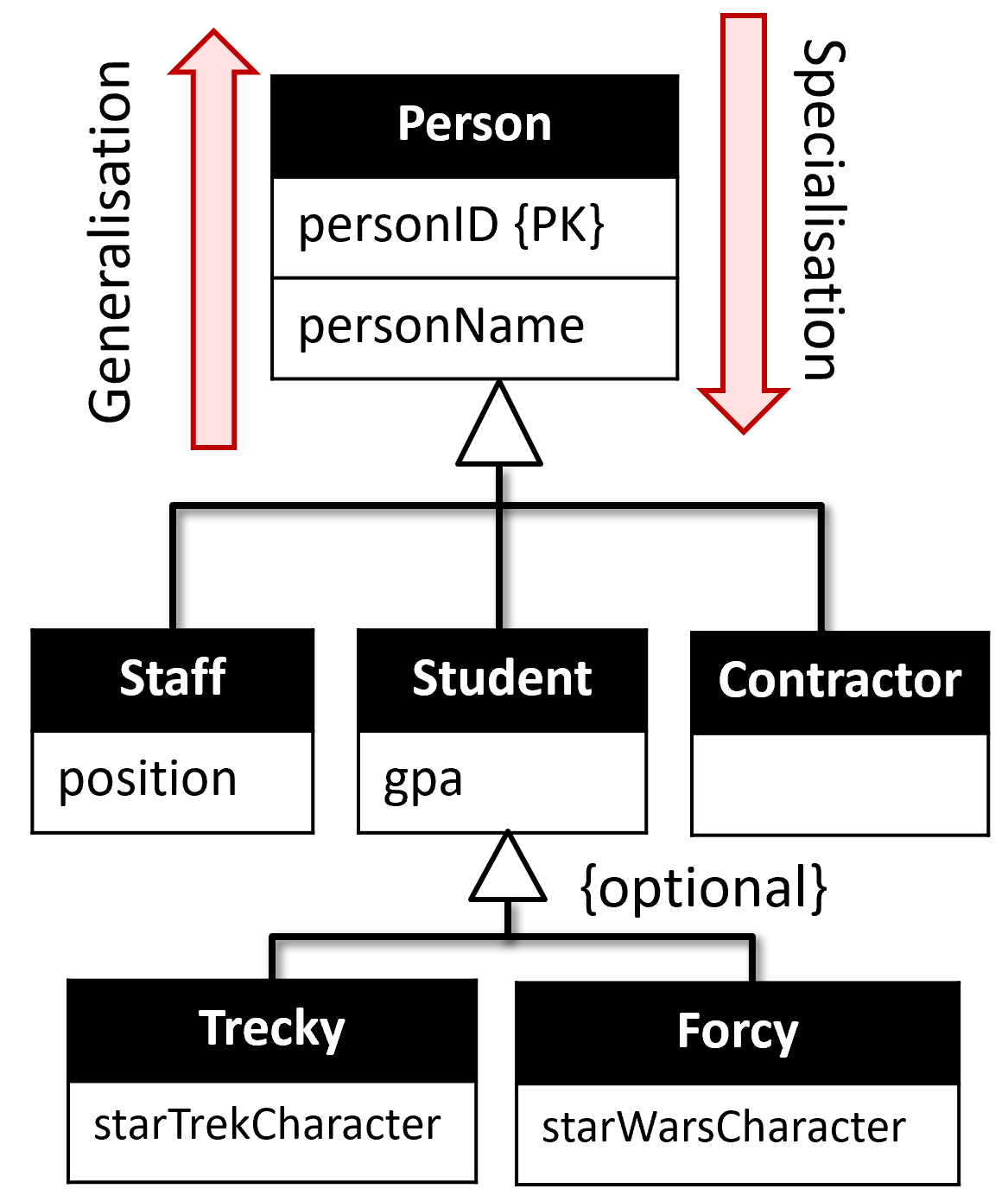
- Specialisation
- The process of identifying distinguishing characteristics of subclasses of a class.
- E.g. John as a student is a more specific example of a person.
- Generalisation
- The process of identifying common characteristics of subclasses for a superclass.
- Constraints on Specialisation / Generalisation
A subclass member is always a member of the superclass.
Optional Participation (default if not specified)
- A person may not be any of a staff member, student, or contractor.
- A person does not need to be a member of any subclass.
Mandatory Participation (must specify)
- A person must be a staff member or a student.
Disjoint (OR)
- Every person is either one of a staff member, student, or contractor.
Non-Disjoint (AND) - overlapping
- Every person is represented by at least two of the sub-classes.
- A person may be a staff member and a student or a student and a contractor, etc.
